Professional 3D Printing Services for Rapid Prototypes and Production Parts
1–5 day standard polymer lead time · 6 technologies · 101 materials · qualified supplier options
3D printing builds metal and plastic parts layer by layer from digital CAD files, enabling complex geometries, rapid iteration, and low-volume production. Use one quoting workflow to compare SLA, SLS, MJF, FDM, PolyJet, and DMLS options against your geometry, material, tolerance, and lead-time target.
Why Choose MakerStage for Industrial 3D Printing
Compare speed, process options, finishing, and volume support for industrial 3D printed parts.
1–5 Business Day Lead Time
Typical lead time for many standard polymer prints
Multi-Technology
SLA, SLS, FDM, MJF, PolyJet, and DMLS technologies available through one quoting workflow. Choose the right process for your application
Professional Secondary Finishing
Process-dependent post-processing including sanding, painting, coating, thread finishing, and plating where applicable
Scalable Volume Support
Prototype one part, then route qualified repeat builds into SLS or MJF batches up to 10,000+ units when the geometry and material are a fit.
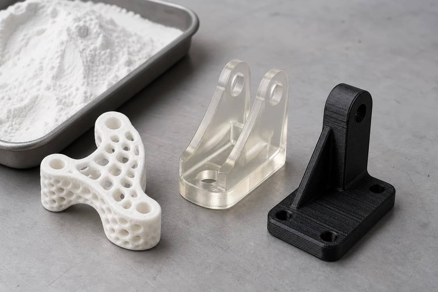
Figure 1. Mixed 3D printed material samples
Use the RFQ to compare resin, nylon, and thermoplastic options against the part geometry and finish target.
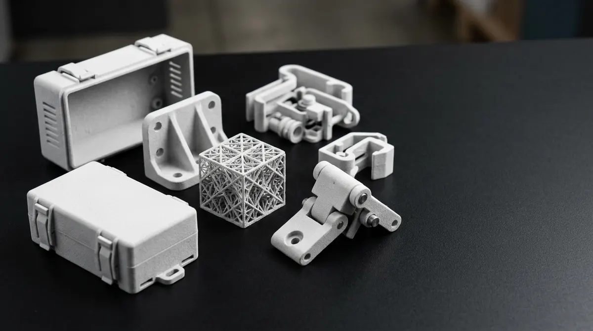
Figure 2. SLS and MJF nylon part collection
Powder-bed nylon processes support functional plastic parts, nested builds, and repeat batches through one quoting workflow.
3D Printing Processes We Support
SLA, SLS, FDM, MJF, PolyJet, and DMLS are available through one quoting workflow. Compare the practical fit for your geometry, material, finish, volume, and budget.
SLA
Stereolithography
SLS
Selective Laser Sintering
MJF
Multi Jet Fusion
FDM
Fused Deposition Modeling
PolyJet
Material Jetting
DMLS
Direct Metal Laser Sintering
Debating whether to bring industrial 3D printing in-house?
Before you buy that next production AM system, run the numbers. See our detailed breakdown of capital equipment, material handling, and hidden operational costs.
Example Parts Across Processes and Materials
Review sample parts across resin, nylon, thermoplastic, and metal workflows before choosing the process that fits the geometry and requirement.
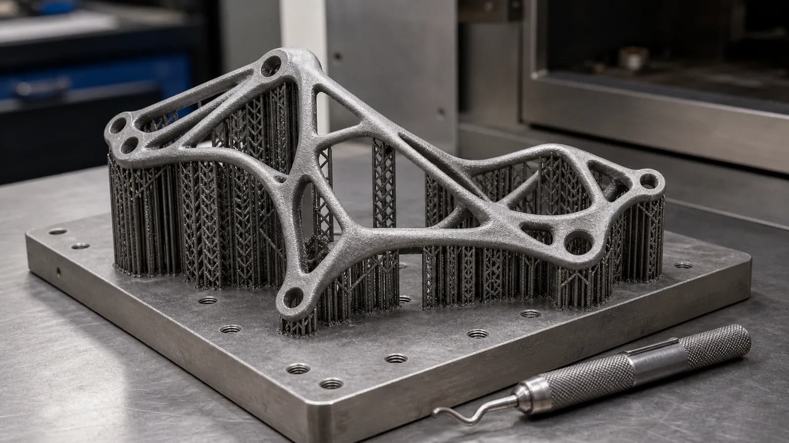
Figure 3. DMLS lattice bracket on a build plate
DMLS is a fit when metal geometry is too complex for a simple machined-from-billet approach.
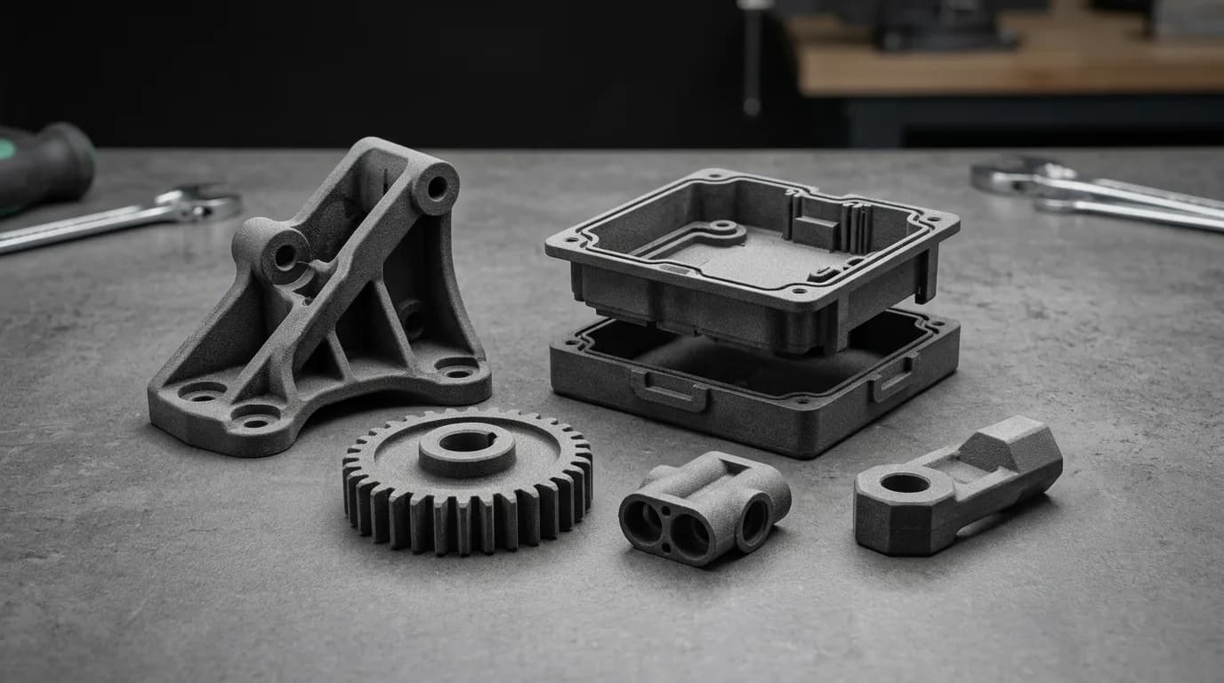
Figure 4. MJF nylon brackets, housings, and duct parts
MJF is often shown in gray or black PA12-style parts for functional brackets, housings, gears, ducts, and repeatable nylon batches.
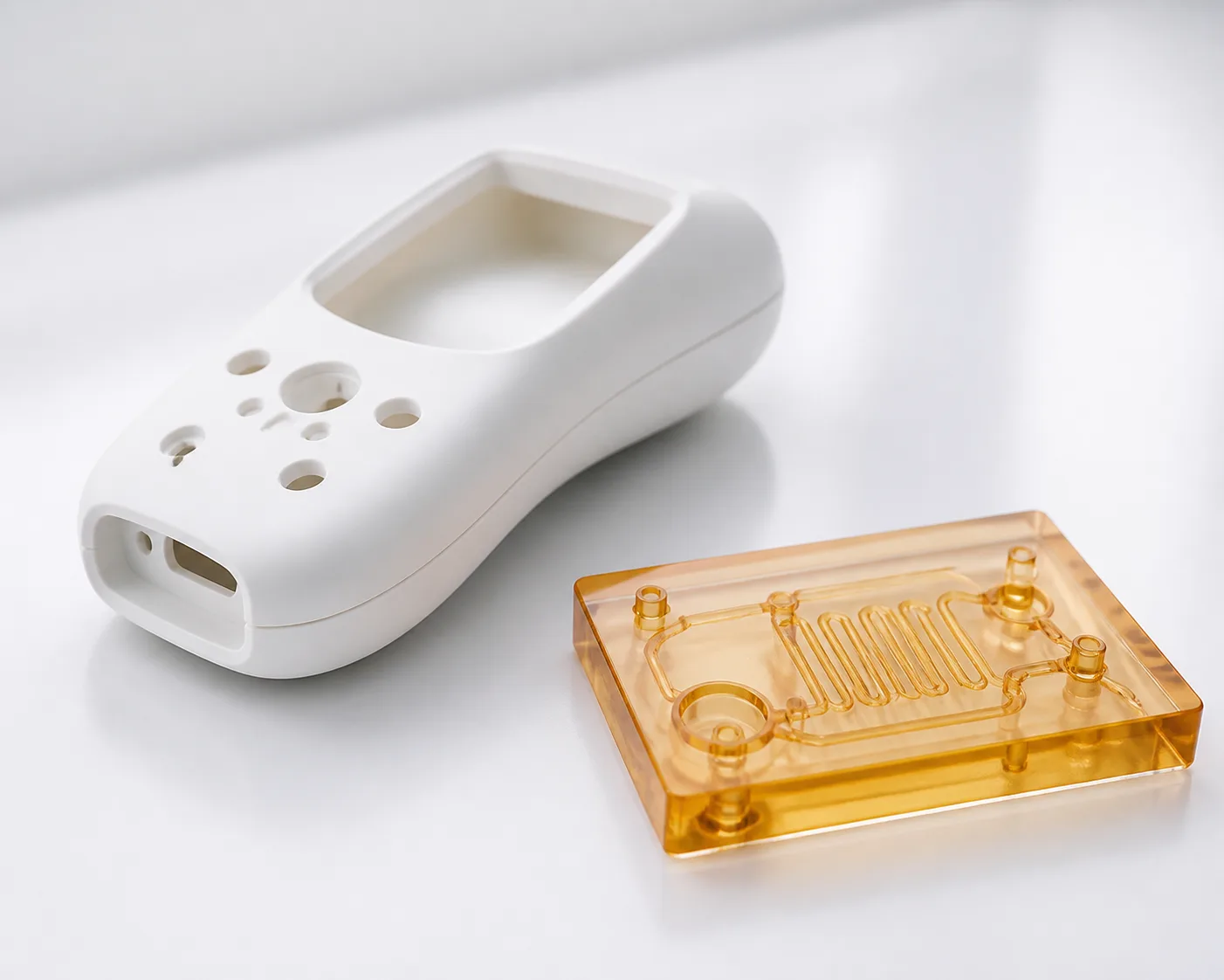
Figure 5. Clear SLA fluid-path and handheld enclosure prototypes
Clear and high-temperature SLA-style resins help teams review optical access, fluid-path geometry, buttons, ports, and handheld enclosure fit before tooling.
Full 6-Technology 3D Printing Comparison
Compare SLA, SLS, FDM, MJF, PolyJet, and DMLS by the practical buying questions engineers usually ask first: finish, tolerance, supports, materials, lead time, per-part cost, and volume.
Decision shortcut
Pick a starting process
SLA / PolyJet
Smooth detail, clear parts, soft-touch appearance models
SLS / MJF
Functional nylon parts, no separate supports when powder can escape, repeat batches
FDM
Large fit checks, fixtures, and fast concept models
DMLS
Dense metal parts where complex geometry earns the cost
Check before quoting
Geometry: supports, cavities, walls, channels
Material: nylon, resin, thermoplastic, metal
Finish: appearance, touch, tolerance, sealing faces
Volume: prototype, pilot run, repeat batch
Full comparison table
SLA vs SLS vs FDM vs MJF vs PolyJet vs DMLS
Scroll horizontally on smaller screens. The first column stays close to the row meaning so each value is easier to review.
| What to compare | SLA | SLS | FDM | MJF | PolyJet | DMLS |
|---|---|---|---|---|---|---|
| Process | UV laser resin curing | CO2 laser powder bed | Thermoplastic extrusion | HP inkjet + IR fusing agent | Inkjet photopolymer jetting + UV cure | Fiber laser metal powder |
| Layer height | 25–100 µm | 60–120 µm | 100–400 µm | 80 µm typical HP MJF | 16–32 µm | 20–60 µm |
| Tolerance | ±0.005 in. (±0.13 mm) | ±0.010 in. (±0.25 mm) | ±0.020 in. (±0.50 mm) | ±0.010–0.012 in. (±0.25–0.30 mm) | ±0.004–0.005 in. (±0.10–0.13 mm) | ±0.003–0.004 in. (±0.08–0.10 mm) |
| Surface finish | Ra 40–120 µin. (1–3 µm) | Ra 240–590 µin. (6–15 µm) | Ra 390–980 µin. (10–25 µm) | Ra 200–400 µin. (5–10 µm) | Ra 40–120 µin. (1–3 µm) | Ra 240–790 µin. (6–20 µm) as-built |
| Supports | Yes | No separate supports; powder escape still needed | Yes above steep overhangs | No separate supports; powder escape still needed | Yes; soluble gel support | Yes |
| Multi-material | No | No | Limited with dual extrusion | No | Yes; rigid, flexible, and transparent in one build | No |
| Key materials | Clear/PC-like, ABS-like Tough, PP/HDPE-like Durable, glass-filled rigid, High-Temp, Flexible 50A/80A-style, Castable | PA12, PA11, PA12-GF, PA12-CF, TPU, PP | PLA, ABS, PETG, Nylon, PC, PEEK, PEI | PA12, PA11, PA12-GB, TPU, PP | VeroWhite, VeroClear, Agilus30, RGD525, MED610/620, Digital ABS Plus | Ti-6Al-4V titanium, 316L/17-4 PH stainless steel, Inconel 625/718, AlSi10Mg aluminum |
| Typical lead time | 1–3 days | 2–4 days | 1–2 days | 2–3 days | 1–3 days | 5–10 days + post-processing |
| Per-part cost | $15–80 | $30–80 | $3–50 | $25–65; small nested PA12 parts can reach $8–20 at 200+ pcs | $50–300; material-intensive | $150–500 |
| Production volume | 1–50 pcs | 1–1,000 pcs | 1–50 pcs | 1–10,000 pcs | 1–25 pcs | 1–100 pcs |
| Good fit | Visual prototypes, fine-detail models, jewelry patterns, master patterns for silicone molds | Functional prototypes, ducting, snap-fits, robotics brackets, small-batch production | Concept models, jigs and fixtures, large-format parts, rapid iteration | Bridge production, automotive interiors, electronics housings, medical-device prototypes, snap-fit enclosures | Multi-material assemblies, ergonomic models, appearance prototypes, overmold simulation, soft-touch jigs | Robotics structural brackets, conformal cooling inserts, medical-device prototype components, high-temp alloy tooling |
Reality check: these values are practical starting points, not blanket guarantees. Actual tolerance, surface finish, lead time, and per-part cost depend on geometry, orientation, nesting, material lot, machine calibration, post-processing, inspection method, and supplier route.
Industrial 3D Printing Materials
101+ materials across SLA resins, SLS/MJF powder-bed plastics, FDM materials commonly used by engineering teams, and DMLS additive metals.
Need material data for heat resistance, flexibility, biocompatible material options, or datasheet-backed flame-retardant grades with UL 94 V-0 ratings? Request datasheets with your RFQ.
SLA Resins
Clear/PC-like, ABS-like Tough, PP/HDPE-like Durable, glass-filled rigid, High-Temp, Flexible 50A/80A-style, and Castable options
Clear / PC-like SLA
Transparent resin for housings and flow checks
ABS-like Tough
Tough resin for enclosures and snap-fit trials
PP / HDPE-like Durable
Compliant resin for clips and impact-prone parts
Glass-filled Rigid
High-stiffness resin for fixtures and tooling
High-Temp SLA
Heat-resistant resin for controlled thermal tests
Flexible 50A / 80A
Elastomeric resin for grips, seals, and pads
Castable
Burnout resin for investment casting patterns
SLS/MJF Powder Bed Plastics
PA12, PA11, glass-filled or glass bead-filled PA12, PP, and TPU options around Shore 88A–95A
PA12 Natural
Functional nylon, chemical resistant
PA12 Glass-filled
Glass-filled or glass bead-filled reinforcement
PA11
Chemical & impact resistant, ductile
PA12-CF
Carbon fiber reinforced
TPU
Flexible elastomer, often Shore 88A–95A
PP
Polypropylene, chemical resistant
FDM Materials
Typically used by engineering teams: PLA, ABS, PETG, TPU, Nylon, PC, PEEK, and PEI/Ultem
PLA Natural
Easy printing, biodegradable
ABS Black
Impact resistant, durable prototype material
PETG Clear
Chemical resistant, translucent prototype material
TPU Flexible
Shore 95A elastomer
Nylon (PA)
Abrasion resistant, jigs & fixtures
PC
Polycarbonate, stronger heat-resistant prototypes
PEEK / PEI
High-temperature engineering thermoplastics
For high-temperature FDM materials such as PEEK and PEI/Ultem, see the FDM 3D printing guide.
DMLS Metal Powders
Titanium, stainless steel, nickel superalloy, and aluminum powder-bed alloys
AlSi10Mg Aluminum
Lightweight aluminum-silicon-magnesium alloy
Ti-6Al-4V Titanium
Titanium Grade 5, high-strength structural
316L Stainless Steel
Corrosion resistant steel
Inconel 625/718
Nickel superalloys for high-temperature use
17-4 PH Stainless Steel
Precipitation hardening stainless
Melting points identify alloy families; service temperature still depends on heat treatment, load, environment, and inspection requirements.
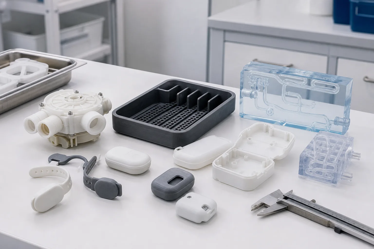
Figure 6. Medical-device prototype housings
Use material selection to compare clear, rigid, and durable resin or nylon options before a housing moves into tooling or machining.
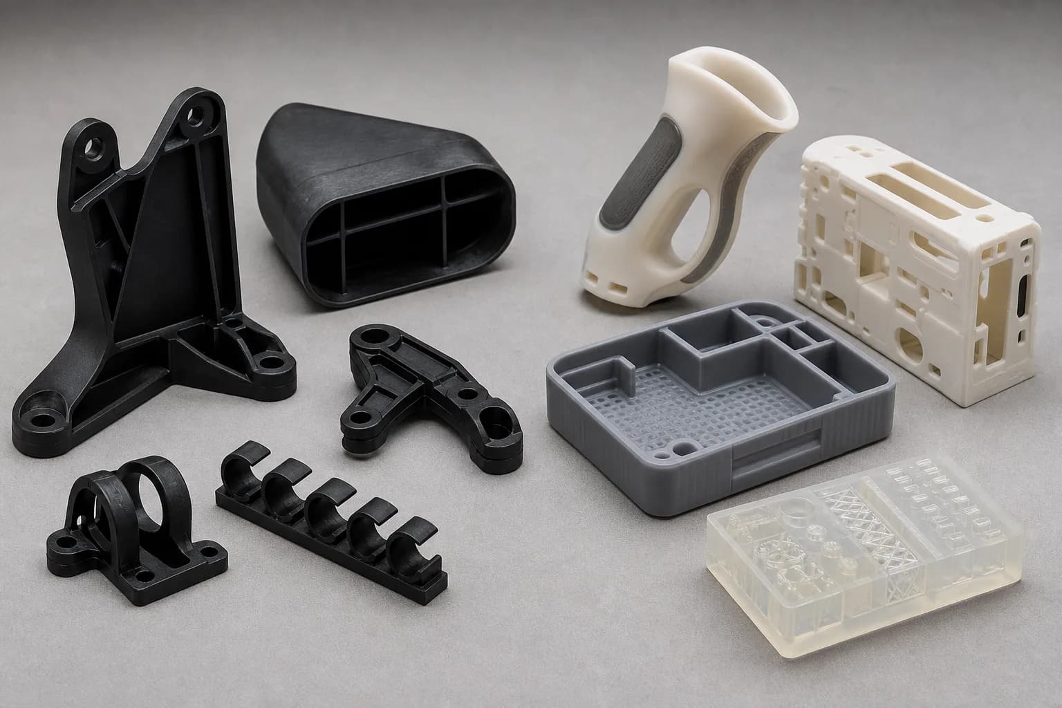
Figure 7. Mixed material prototype part set
Mixed part families help teams review color, stiffness, transparency, and surface finish requirements across several process choices.
Material Selection Guide
Visual Prototypes
Resins for appearance models and presentation parts
Functional Testing
Nylon powders for mechanical validation
Rapid Iteration
Filaments for early concept development
Production Parts
Metal powders for end-use components
Design Checks Before You Upload a 3D Printing RFQ
Use these starting points to choose a process, flag risky features, and decide where secondary machining is needed.
Process-specific tolerance and wall-thickness starting points
SLA
- Typical tolerance
- ±0.005 in. (±0.13 mm)
- Minimum wall
- 0.020 in. (0.50 mm)
- Good fit
- Smooth visual prototypes, fine ribs, snap-fit checks
SLS
- Typical tolerance
- ±0.010 in. (±0.25 mm)
- Minimum wall
- 0.030 in. (0.75 mm)
- Good fit
- Durable nylon brackets, ducting, living hinges
MJF
- Typical tolerance
- ±0.010–0.012 in. (±0.25–0.30 mm)
- Minimum wall
- 0.030 in. (0.75 mm)
- Good fit
- Repeatable PA12 batches and nested assemblies
FDM
- Typical tolerance
- ±0.020 in. (±0.50 mm)
- Minimum wall
- 0.040 in. (1.00 mm)
- Good fit
- Large fixtures, early concept models, check gauges
PolyJet
- Typical tolerance
- ±0.004–0.005 in. (±0.10–0.13 mm)
- Minimum wall
- 0.024 in. (0.60 mm)
- Good fit
- Multi-material appearance models and soft-touch details
DMLS
- Typical tolerance
- ±0.003–0.004 in. (±0.08–0.10 mm)
- Minimum wall
- 0.030 in. (0.75 mm)
- Good fit
- Metal brackets, manifolds, inserts, and tooling
Minimum Feature and Wall Thickness
Keep load-bearing walls near or above the process minimum and add ribs or fillets when thin walls connect to bosses. Small pins, clips, and snap features should be checked against the material's elongation and build orientation.
Designing for Powder Bed vs. Resin
Powder-bed parts such as SLS and MJF can build unsupported internal passages, but trapped powder needs escape paths. Resin parts can produce sharper cosmetic detail, but supports and orientation can affect visible surfaces.
Dimensional Limits and Critical Datums
Treat build volume, shrinkage, and thermal stress as process constraints. For tight bores, sealing faces, threaded holes, or bearing seats, specify the datum and plan for secondary CNC machining after printing.
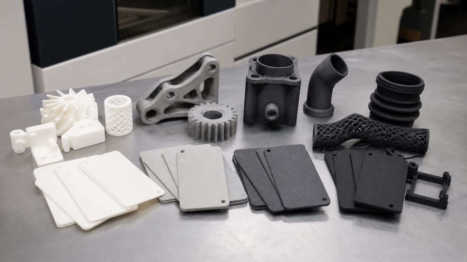
Figure 8. Mixed MJF polymer prototype parts
Part families with brackets, housings, and flat panels should be reviewed together so tolerance and finish expectations stay consistent.
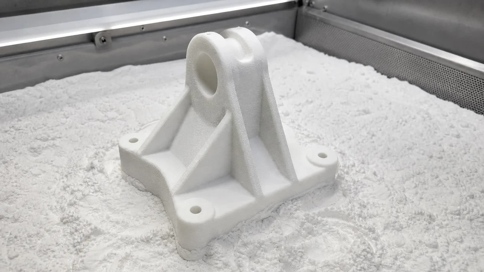
Figure 9. Powder-bed printed bracket in nylon powder
Orientation, powder removal, wall thickness, and datums should be considered before moving a bracket design into repeat builds.
Prefer
Uniform walls, generous fillets, powder escape holes, and machined datums called out on the drawing.
Avoid
Knife edges, unsupported long pins, sealed hollow volumes, and tolerance stacks copied from CNC drawings without process review.
Professional Post-Processing and Surface Finishing
Post-processing turns a printed build into a usable prototype, sales sample, fixture, or low-volume production part.
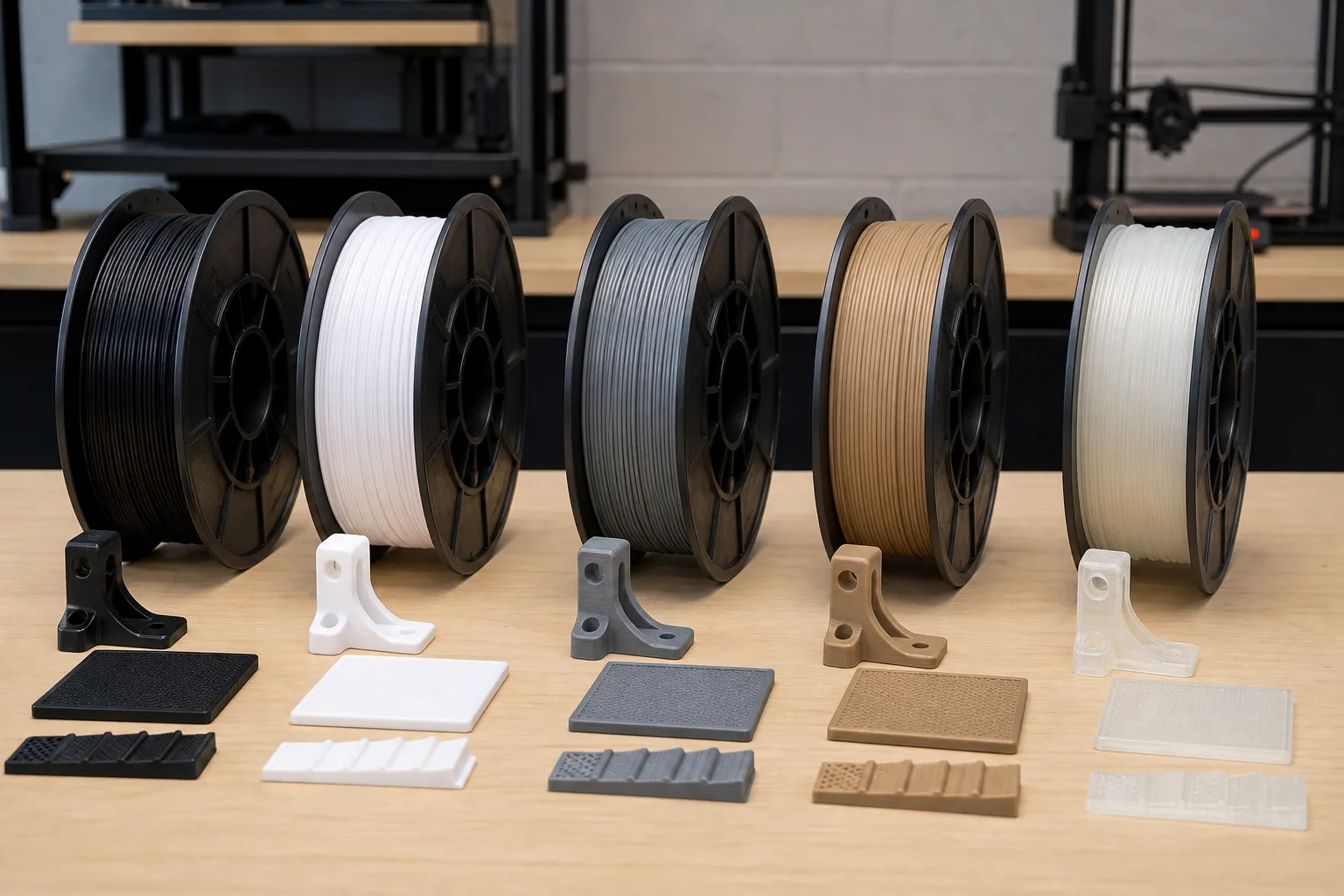
Figure 10. FDM filament materials and printed samples
Filament choice changes stiffness, heat behavior, color, and surface texture for early prototypes and fixtures.
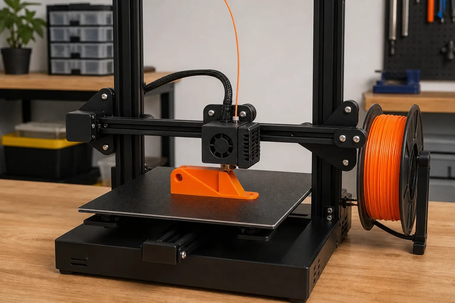
Figure 11. FDM orange thermoplastic part in progress
FDM keeps early concept iteration simple when the main question is size, fit, or handling rather than final cosmetics.
Cosmetic Finishing
Sanding, priming, painting, clear coating, and color matching for appearance prototypes that need to look close to molded production parts.
Functional Finishing
Vapor smoothing, dyeing, media tumbling, bead blasting, heat-set inserts, and thread tapping for parts that must assemble, handle wear, or pass fit checks.
Technical Finishing
Stress relief, bead blasting, passivation where applicable, and CNC secondary machining for critical metal and plastic printed features.
3D Printing for Industry Applications
Choose the process around the part's job: fit check, functional test, end-of-arm tooling, appearance model, or low-volume end-use component.
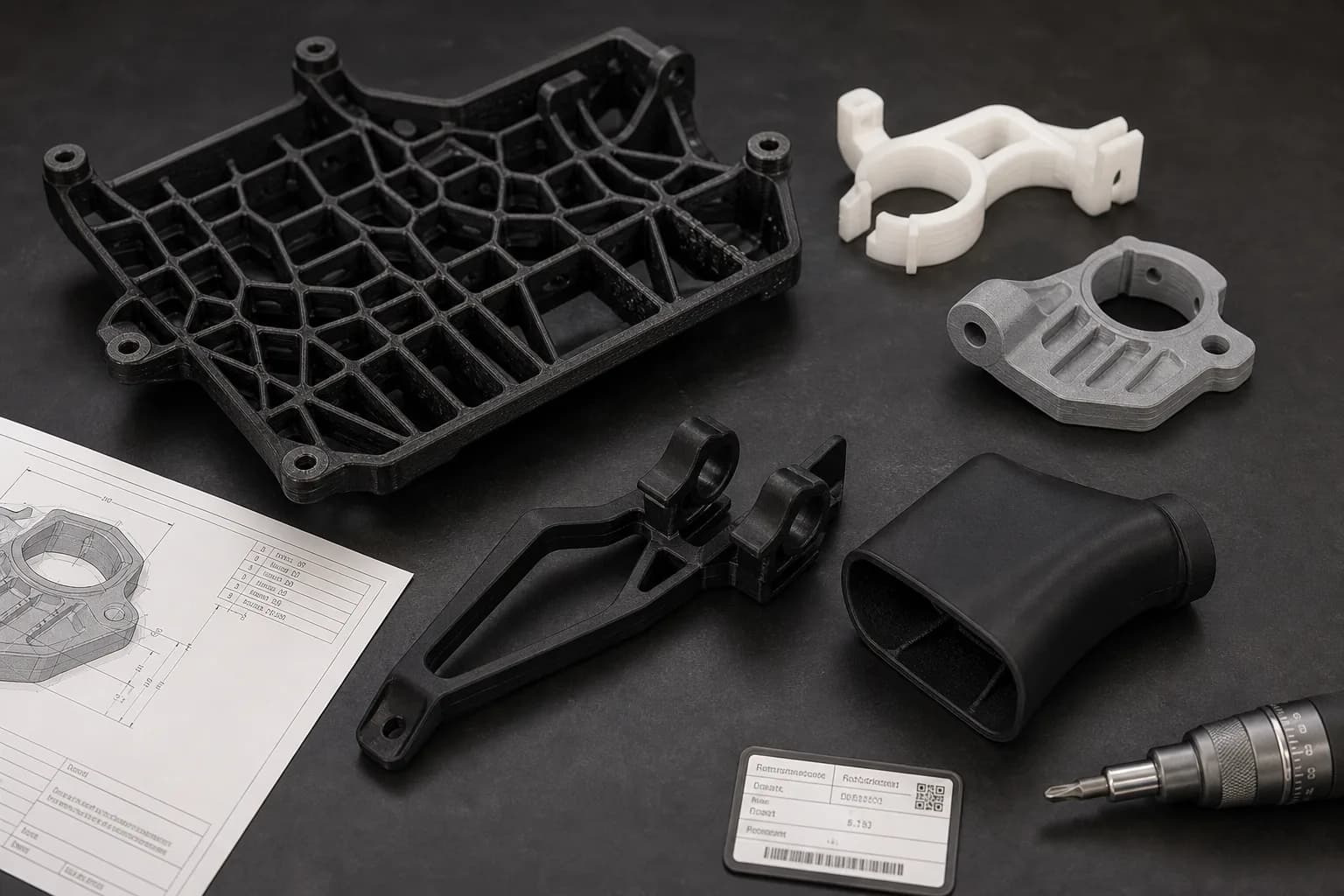
Figure 12. Automotive brackets, ducts, and clips
Automotive & Transportation
Lightweight brackets, ducting, clips, sensor mounts, and routing prototypes for fit checks before production choices are locked.
Bracket, duct, clip, and sensor-mount prototypes help teams check fit, routing, and lightweight geometry before production choices are locked.
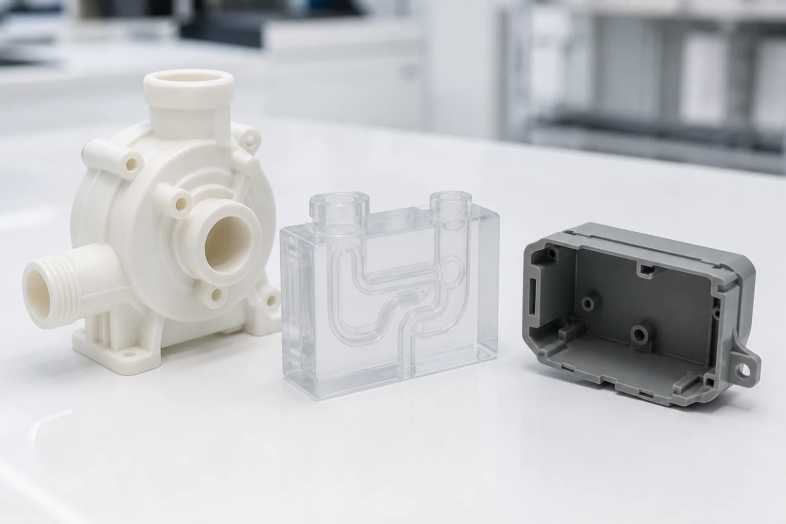
Figure 13. Pump housing, fluid block, and enclosure prototypes
Medical & Life Sciences
Pump housings, sensor enclosures, fluid-path demonstration blocks, and ergonomic prototypes for early design review.
Small housings and fluid-path demonstration blocks can be printed to review assembly clearances, access points, and handling before the design moves forward.
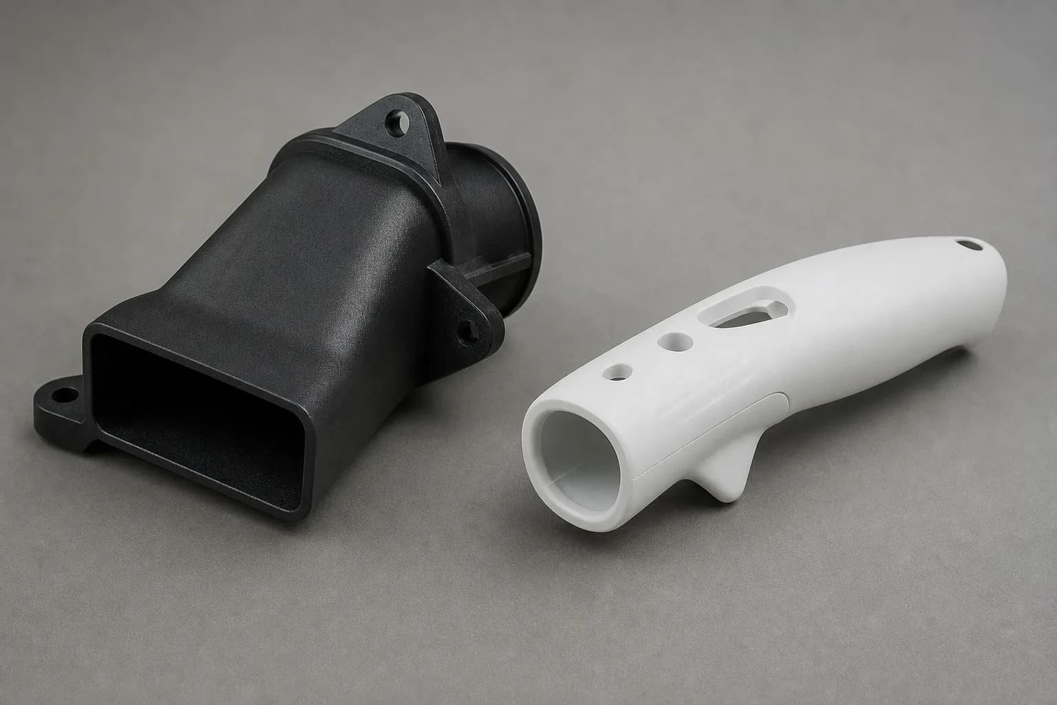
Figure 14. Duct and ergonomic handle prototypes
Product Design & Ergonomics
Handheld housings, airflow shapes, presentation models, and human-factor prototypes for appearance and handling reviews.
3D printing helps compare very different part types in one workflow, from airflow geometry to handheld ergonomic trials.
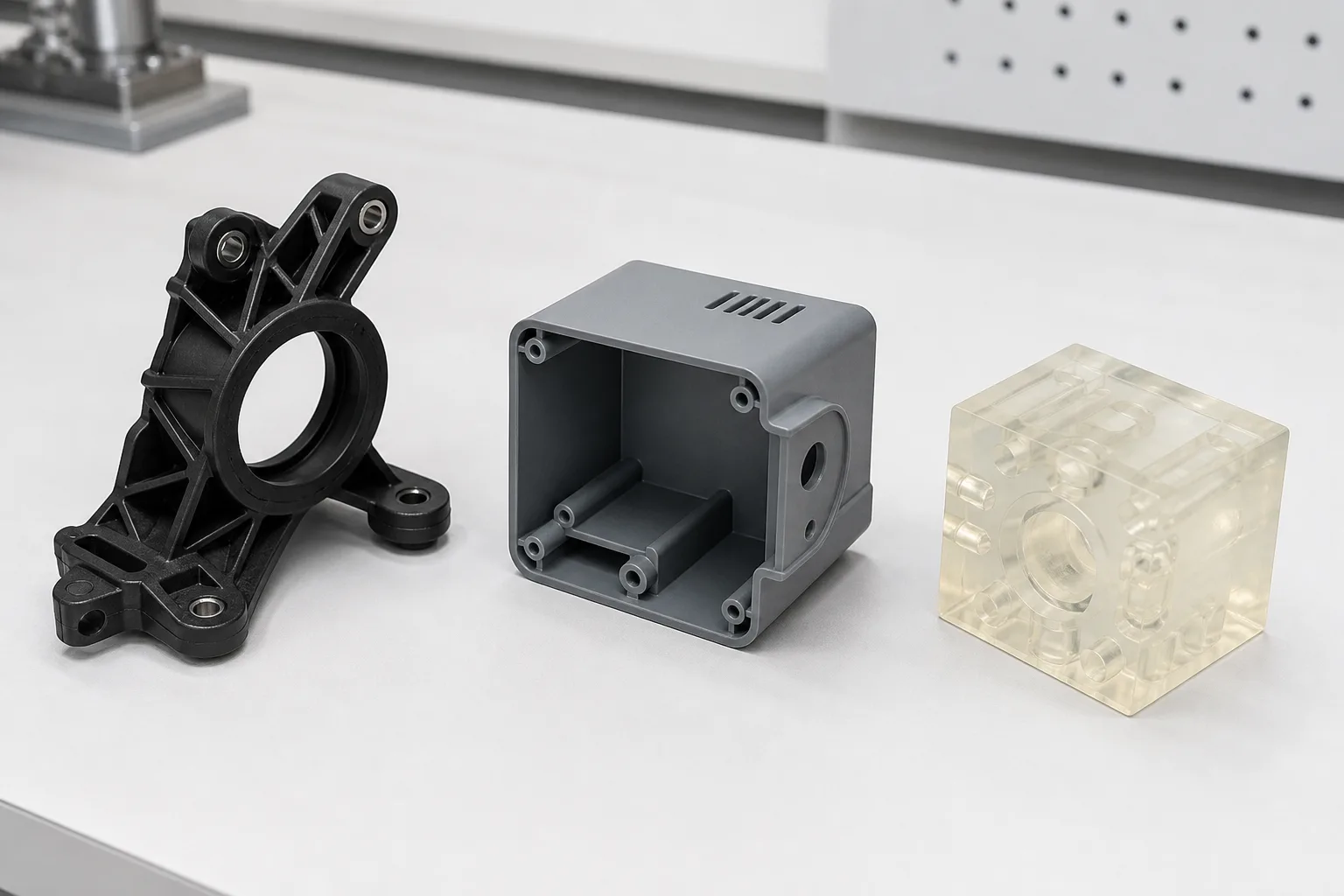
Figure 15. Bracket, housing, and inspection block prototypes
Industrial Automation & Inspection
Robot-cell brackets, electronics housings, fixture concepts, inspection blocks, and assembly aids for low-volume trials.
Mixed geometry sets make it easier to review brackets, enclosures, and transparent inspection features against different process choices.
Metal 3D Printing Services for Complex, Low-Volume Parts
When geometry rules out easy machining or when you need internal channels, lattice structures, or consolidated assemblies, metal 3D printing becomes the more practical path. DMLS is a common route for dense metal parts in Ti-6Al-4V titanium, 316L stainless steel, 17-4 PH stainless steel, Inconel 625/718 nickel superalloys, and AlSi10Mg aluminum, while secondary machining can finish sealing faces, threads, and tight datums after the build.
For a process-by-process breakdown, see the DMLS metal 3D printing guide for alloy selection, post-processing limits, and cost drivers.
Common metal printing use cases
3D Printing FAQs
Common questions about our 3D printing services and technologies.
3D Printing Resources
Deep-dive guides on every technology we offer — materials, design rules, tolerances, and cost data.