Robotics components
Robotics Industry Manufacturing
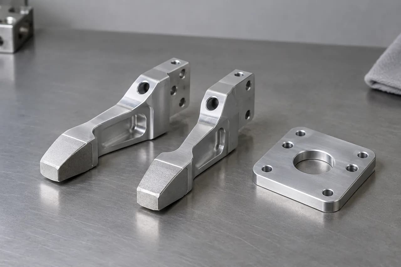
CNC machining, 3D printing, sheet metal fabrication, and finishing for actuator housings, joint brackets, gripper fingers, sensor mounts, and chassis parts.
Have FAR requirements? See how to share them.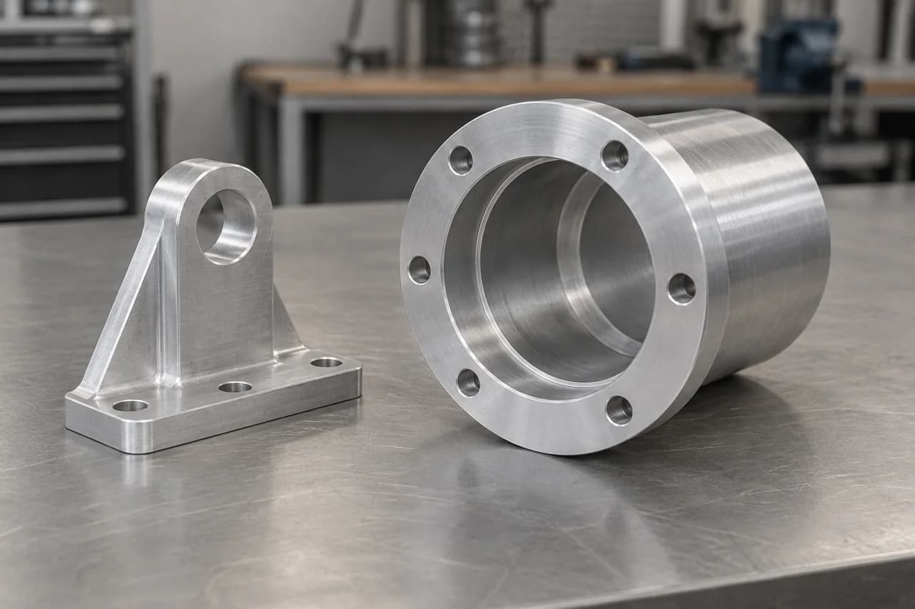
Why Robotics Engineers Choose MakerStage
Our specialized robotics manufacturing combines precision engineering, rapid prototyping, and deep understanding of automation requirements.
If your design problem is closer to cleanroom tooling or outdoor motion hardware, compare semiconductor manufacturing for test fixtures and solar energy manufacturing for tracker hardware.
Precision Engineering
Tolerances as tight as ±0.0002" for critical robotic components
Rapid Prototyping
Typical 10-15 day turnaround for robotics prototypes and custom parts
Material Expertise
147+ materials including aluminum, steel, titanium, and engineering plastics
Inspection & Documentation
Request CMM inspection, dimensional reports, and material certificates with your RFQ
Robotics Manufacturing Capabilities
Specialized processes and precision equipment for robotics components, including machined housings, printed prototypes, fabricated enclosures, and surface finishes.
Precision CNC Machining
3-Axis & 5-Axis Capabilities
Robotics Specifications
±0.0005" standard
Ra 0.8µm standard
24" x 16" x 12"
Typically 10-15 days
Robotics Materials
Robotics Applications
- Robotic arm joints and links
- Actuator housings and mounts
- Precision gears and couplings
- Custom robotic chassis
Learn more about CNC machining →
Debating in-house vs. outsourcing for joints and housings? Our In-House vs. Outsource Analysis includes a full cost breakdown for a 304 stainless steel robotic wrist joint housing.
Rapid Prototyping 3D Printing
Multiple Technologies
Prototyping Specifications
25µm (SLA)
±0.1mm typical
16" x 16" x 20"
1–5 days
3D Printing Materials
Robotics Applications
- Rapid concept prototypes
- Custom gripper fingers
- Sensor mounting brackets
- Flexible joint components
Sheet Metal Fabrication
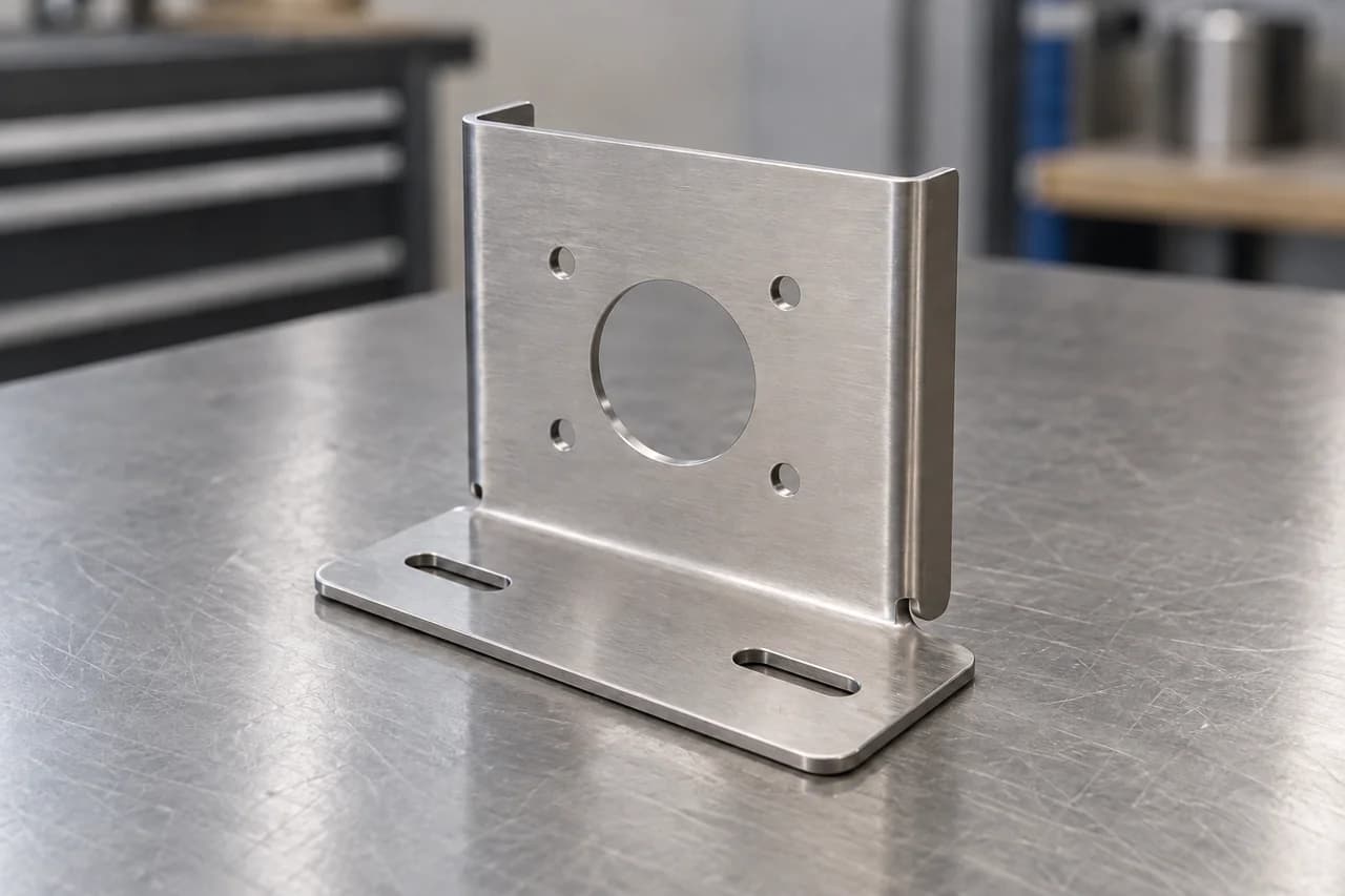
Brackets, panels, and enclosures
Fabricated components for robot chassis, equipment housings, and sensor mounts. Share your drawings, material, thickness, and finish requirements so the manufacturing scope can be quoted.
Robotics Applications
- Chassis panels
- Sensor mounting brackets
- Equipment enclosures
- Battery compartment panels
Surface Finishing & Treatment
Enhanced Durability
Finishing Specifications
Ra 0.4µm achievable
±0.0005" control
Industrial grade
Typically 10-15 days
Surface Treatments
Robotics Applications
- Wear-resistant surfaces
- Corrosion protection
- Aesthetic finishes
- Electrical insulation
Robotics & Automation Applications
We manufacture precision components for the complete robotics ecosystem, from industrial automation to collaborative robots and autonomous systems.
Industrial Robotics
Heavy-duty industrial robots requiring precision and durability
- Robotic arm joints and links
- Actuator housings and mounts
- Precision gearbox components
- End-effector components
Collaborative Robots (Cobots)
Human-robot collaboration requiring safety and precision
- Lightweight joint mechanisms
- Safety sensor mounts
- Flexible gripper components
- Human-safe housing designs
Automation Systems
Factory automation requiring high-speed, precise operation
- Linear actuator components
- Conveyor system parts
- Pick-and-place mechanisms
- Sorting system components
Mobile Robotics
Autonomous mobile robots requiring lightweight, durable structures
- Chassis and frame components
- Wheel and drive components
- Sensor mounting systems
- Battery compartments
Robotic Grippers & Tools
Specialized gripping and manipulation requiring custom solutions
- Pneumatic gripper jaws
- Electric gripper mechanisms
- Tool changer interfaces
- Custom end-effectors
Sensor & Vision Systems
Robotic perception systems requiring precise positioning and protection
- Camera mounting brackets
- LIDAR sensor housings
- Force sensor mounts
- Environmental protection enclosures
Have FAR requirements for your parts?
Share Federal Acquisition Regulation (FAR) requirements with your robotics RFQ. This optional step helps us review the requirements that apply to your parts.
Share requirements PDFs
Open Customer or contract requirements in the RFQ and select Yes or Not sure for FAR. Upload multiple PDFs, or submit your RFQ and provide the documents later.
Connect documents to parts
Expand each document to add its reference or revision and the parts it applies to. Keep requirements documents separate from your part drawings.
Confirm the scope
Requirements remain pending review. Manufacturing location is selected separately and confirmed along with the requirements before an order is accepted.
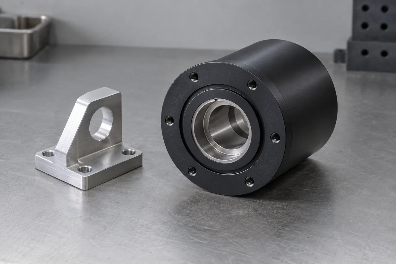
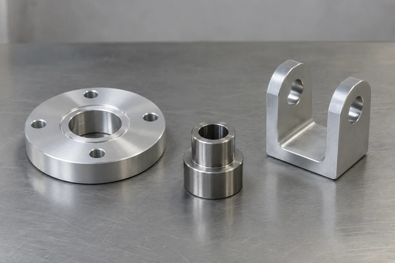
Illustrative component examples
View the component geometry, mounting features and interfaces in each image.
Robotics Manufacturing FAQ
Common questions from robotics engineers about our precision manufacturing capabilities.
Related Manufacturing Pages
These links connect robotics buyers to adjacent precision workflows and a stronger RFQ starting point.
A useful comparison if your robotics build is closer to ultra-precision tooling, carrier plates, or inspection hardware.
Helpful when your motion system overlaps with actuator brackets, sensor mounts, or outdoor drivetrain components.
Use this before quoting actuator housings, grippers, brackets, or fixtures that need clear tolerances and inspection scope.
Related Resources
Cost analysis, supplier qualification, and change control for robotics and automation sourcing.
Ready to Build Your Next Robot?
Share your part drawings, quantities, inspection needs, and customer requirements to request a robotics manufacturing quote.