Sheet Metal Fabrication
±0.005" cutting · 5–15 days lead time · 6+ material families
From laser-cut blanks to powder-coated enclosures, PEM-ready brackets, and formed panels, sheet metal fabrication turns flat stock into finished hardware through cutting, bending, welding, and finishing. Laser cutting, CNC bending, and coordinated secondary operations support production-intent parts with fewer handoff delays.
Project examples
Sheet Metal Parts in the Shop
See how cut blanks, press brake forming, and enclosure chassis work show up across common sheet metal fabrication jobs.
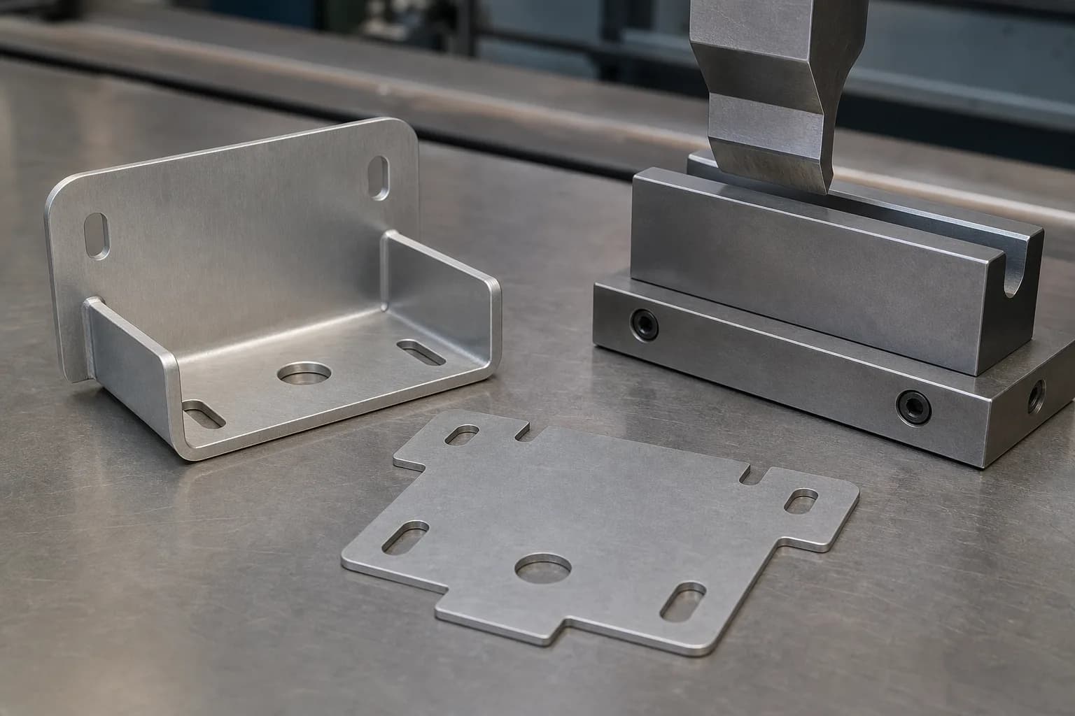
Flat blank to formed bracket
Figure 1. A cut blank and formed bracket show how flat stock becomes bent sheet metal geometry after press brake forming.

Press brake forming
Figure 2. Press brake tooling forms a controlled bend in a sheet metal blank before the part moves to hardware insertion, welding, or finishing.

Formed enclosure chassis
Figure 3. Formed enclosure chassis can include cutouts, mounting flanges, joined corners, and installed threaded hardware.
End-to-End Sheet Metal Fabrication
Laser cutting, CNC bending, welding, hardware insertion, and finishing — coordinated in one workflow for quality control and shorter handoff delays.
High-Precision Cutting
Fiber laser cutting to ±0.005" on sheets up to 48" × 120". Clean edges, minimal HAZ, and burr-free finishes on aluminum, stainless, and carbon steel.
Complex Forming
CNC press brake bending up to 12 ft with air bending and bottoming. Multi-bend assemblies, tight radii, and repeatable angles across production runs.
Full Finishing Suite
Powder coating (any RAL color), anodizing (Type II & III), plating (zinc, nickel, chrome), passivation, brushing, and bead blasting — all coordinated in one order.
Our Process
Rapid Sheet Metal Prototyping for Fit, Form, and Early Production
Rapid sheet metal work is often the shortest path when you need production-intent brackets, covers, trays, or enclosures before committing to a larger release. Laser-cut flat patterns and simple bent parts typically move more quickly than welded, hardware-heavy assemblies because there are fewer secondary operations to schedule and inspect.
Typical lead-time ranges
Choose Your Process
Every sheet metal job combines one or more of these processes. We handle the full workflow so you get finished parts, not half-done blanks.
Laser Cutting
Best For
- Complex 2D profiles and cutouts
- Prototypes through high-volume blanks
- Thin-gauge decorative panels
Press Brake Forming
Best For
- Enclosures, chassis, and U-channels
- Multi-bend structural brackets
- Production runs requiring repeatable angles
Welding & Assembly
Best For
- Weldments and multi-part assemblies
- Structural frames and mounting plates
- Cosmetic weld-and-grind finishes
| Feature | Laser Cutting | Press Brake | Welding |
|---|---|---|---|
| Typical Tolerance | ±0.005" | ±0.010" | ±0.030" |
| Max Part Size | 48" × 120" | 12 ft length | Assembly-dependent |
| Material Thickness | 0.020"–0.500" | 0.020"–0.250" | 0.020"–0.250" |
| Surface Finish | Burr-free edge | Tooling marks on bend | Grind / dress available |
| Best Volume | 1–10,000+ | 1–10,000+ | 1–1,000 |
Process fit check
Not sure whether laser cutting, bending, or welding fits your part?
Upload your STEP, DXF, or drawing and get an engineer-reviewed sheet metal quote with manufacturability feedback on material, bend strategy, hardware, and finish risks.
Manufacturing process fit
Sheet Metal, CNC Machining, or 3D Printing?
Use the process that matches the starting stock and final part function. Sheet metal starts as flat stock, CNC starts from billet or plate, and 3D printing builds geometry layer by layer.
| Process | Best Fit | Watch Before Quoting | Route |
|---|---|---|---|
| Sheet Metal Fabrication | Brackets, panels, enclosures, chassis, shields, and formed thin-gauge hardware. | Bend radius, hole-to-bend distance, grain direction, hardware insertion, and finish after forming. | Current page |
| CNC Machining | Solid blocks, housings, fixtures, tight 3D features, precision bores, and datum-controlled faces. | Machine access, setup count, deep pockets, material removal, and ±0.005" standard tolerance needs. | CNC machining |
| 3D Printing | Fast prototypes, complex geometry, ergonomic forms, lightweight internal features, and low-volume validation. | Material family, build orientation, layer lines, heat exposure, finish expectations, and process-dependent tolerances. | 3D printing |
Debating whether to bring sheet metal fabrication in-house?
Before you buy that next press brake or laser cutter, run the numbers. See our detailed breakdown of capital equipment, labor rates, and hidden operational costs.
Stock Materials
We keep common gauges in stock to reduce material lead-time delays. Less common alloys or tempers may extend quoting and scheduling timelines.
Aluminum Alloys
Excellent formability and corrosion resistance. The most common sheet metal aluminum.
Higher strength, good weldability. Ideal for structural brackets and frames.
Cost-effective general purpose. Great for non-structural enclosures and shields.
Steel Alloys
The workhorse — excellent corrosion resistance for food, medical, and outdoor use.
Superior chemical resistance. Required for marine, chemical, and pharmaceutical.
Low-cost structural steel. Ideal for welded frames, bases, and mounting plates.
Cold-rolled, smooth finish. Good for enclosures that will be powder coated.
Zinc-coated for corrosion protection without additional finishing.
Specialty Metals
High electrical and thermal conductivity. Used for bus bars, heat sinks, and RF shields.
Corrosion-resistant with an attractive finish. Common for decorative panels and connectors.
Designing with copper sheet?
Copper behaves differently from aluminum or steel on cut-edge oxidation, bend radius, and plating. Read our copper sheet metal fabrication guide for bus bars, shields, and heat spreaders.
Not sure which alloy?
Upload your design and our engineers will recommend the optimal material based on your application, environment, and budget.
Surface Finishes for Sheet Metal Parts
Finish changes more than appearance. It can affect corrosion resistance, masking, bend marks, threaded hardware, inspection timing, and whether final dimensions are measured before or after coating.
Raw / as-cut
Fast prototypes, hidden brackets, and parts that will be finished by your team.
Powder coating
Durable color for enclosures, control panels, chassis, and consumer-facing housings.
Anodizing
Type II or Type III aluminum finishes for corrosion resistance, wear resistance, and cosmetic control.
Passivation
Stainless steel parts where the passive chromium-oxide layer matters for corrosion behavior.
Plating
Zinc, nickel, chrome, or project-specific plating for corrosion, wear, or electrical requirements.
Brushing, bead blasting, and marking
Cosmetic texture, glare reduction, panel labels, logos, and operator-facing sheet metal assemblies.
Add finish requirements, masked areas, color callouts, and inspection condition to the drawing when they affect fit or appearance.
Compare finishesSheet Metal Parts Across Industries
From rack-mount server enclosures to robotics structural brackets — our sheet metal capabilities support common hardware sectors.
Enclosures & Chassis
Server racks, telecom housings, control panels, battery enclosures, and consumer electronics chassis — laser cut, formed, welded, and powder coated as turnkey assemblies.
Structural Brackets & Mounts
Load-bearing brackets, mounting plates, gussets, and weldments for medical, robotics, and automotive applications — engineered for strength and weight.
Sheet Metal DFM Tips
Follow these rules to reduce cost, shorten lead time, and improve part quality. Our engineers review every order for DFM — but designing it right upfront saves everyone time.
Minimum Bend Radius
Going below the minimum radius causes cracking on the outside of the bend, especially in work-hardened alloys like 5052-H32.
Minimum Flange Length
Short flanges slip off the press brake die and produce inconsistent angles. A longer flange gives the tooling enough material to grip.
Hole-to-Edge Spacing
Holes too close to an edge will deform during bending or shearing, causing bulging and dimensional loss.
Hole-to-Bend Spacing
The material in the bend zone stretches. Holes placed inside this zone will warp into ovals and lose concentricity.
Relief Cuts
Without relief cuts, the material tears or buckles at the intersection. A small notch lets the bend form cleanly.
K-Factor & Bend Deduction
The K-factor determines how much material is consumed by each bend. Getting it right means your flat pattern unfolds to the correct 3D shape.
Sheet Metal FAQ
Common questions about our sheet metal fabrication services
Related Resources
DFM tips, material selection, and how to prepare your RFQ for faster quotes.
Ready to Start Your Sheet Metal Project?
Upload your STEP or DXF file and get engineer-reviewed sheet metal pricing typically within one business day. Free DFM starts after order confirmation.
Get Free Quote Fast