MJF 3D Printing Services for Functional Nylon Parts
Multi Jet Fusion (MJF) produces detailed PA12 Nylon, PA11 Nylon, and grade-specific flexible parts without production tooling. MakerStage reviews how parts are arranged within a build (nesting), powder removal, finishing, inspection, and repeat-batch requirements before routing the job.
Design for manufacturability (DFM) means checking whether a design can be made as specified. DFM review begins after order confirmation.
Process
Polymer powder bed
Geometry
No dedicated supports
Production
Prototype to repeat batch
- MJF quote response is within 24 hours for standard requests
- DFM review begins after order confirmation
- ISO 9001 certified partner options available when specified in the RFQ
- Material, finish, critical dimensions, and inspection scope reviewed before production
No production tooling
Revise CAD between builds without cutting a mold.
Batch-aware quoting
Quantity, nesting, cooling, and finishing shape the route.
Inspection by requirement
Define datums, reports, and acceptance limits in the RFQ.
Production-minded nylon parts without a mold
MJF is often a strong candidate when functional geometry, repeat quantity, and packed build utilization matter together.
Nested repeat batches
Pack many parts through the build volume when geometry, quantity, and schedule support efficient nesting.
Complex functional geometry
Produce ducts, clips, brackets, housings, and consolidated assemblies without dedicated printed supports.
Functional nylon options
Select PA12 Nylon, PA11 Nylon, glass bead-filled PA12, or a grade-specific thermoplastic polyurethane (TPU) around the actual duty cycle.
Prototype-to-production continuity
Keep the same core process while drawings, finishing, inspection, and batch controls mature with the part.
Area-wide agent jetting, thermal fusion, and controlled cooling
MJF uses fusing and detailing agents to control where thermal energy fuses a polymer-powder layer. The agents assist fusion; they do not glue the powder.
Review the five-step workflow and depowdering requirements
Spread powder
A thin polymer-powder layer is spread across the build bed.
Jet agents
Inkjet heads place fusing and detailing agents across selected regions.
Apply heat
Thermal energy fuses the selected regions while detailing controls edges.
Cool and unpack
The build cools before parts are removed from the surrounding powder.
Clean and finish
Parts are depowdered, commonly bead blasted, then receive quoted finishing.
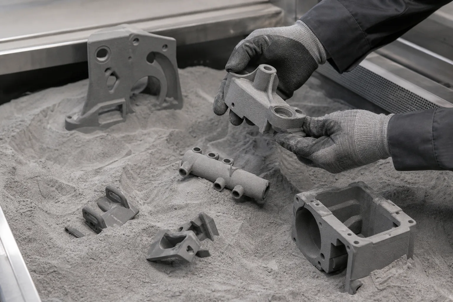
Cooling and powder removal
Support-free does not mean post-process-free
Figure 3. Illustration of gloved handling of gray parts in a powder bed. Unfused powder supports the build, but parts still need cooling, unpacking, powder removal, cleaning, and the finish defined in the quote.
Choose the grade around load, flex, temperature, and finish
PA means polyamide, the nylon family; PA12 and PA11 are different nylon chemistries. Availability and printer compatibility vary by grade and supplier system. The quote confirms the exact material, color, data sheet, finish, and inspection scope.
Versatile default
PA12 Nylon
A balanced option for detailed housings, brackets, enclosures, fixtures, and consolidated functional parts.
Ductility and impact
PA11 Nylon
Evaluate for snap fits, clips, living hinges, and applications where flexibility and impact behavior matter.
40% glass bead-filled
PA12 GB
Evaluate when stiffness and dimensional stability matter more than ductility, including fixtures and housings.
Grade-specific flexibility
TPU
Evaluate exact grades for seals, protective features, cushioning, rebound, and fatigue-resistant flexible parts.
Use design values as starting points, not acceptance limits
Design for manufacturability (DFM) means checking whether a design can be made as specified. The values below come from HP design guidance for PA12, PA12 GB, and PA11. They help prepare the RFQ and later DFM review but do not replace a drawing, supplier capability review, or application validation.
This table scrolls horizontally on smaller screens. Focus the table region and use the left and right arrow keys or swipe to review all columns.
| Feature | HP guidance starting point | What the quote must review |
|---|---|---|
| Short walls | 0.020 in (0.5 mm); selected short walls in the horizontal build plane (XY) may begin at 0.012 in (0.3 mm) | Functional and load-bearing walls normally need more thickness than the printable minimum. |
| Mating interfaces | 0.016 in (0.4 mm) gap | Fit depends on interface length, orientation, finish, and whether the faces can be measured. |
| Print-in-place moving faces | 0.028 in (0.7 mm) clearance | Provide powder-removal access and expect iteration for long or shielded interfaces. |
| Hollow shells | 0.079 in (2.0 mm) wall with drain access | Enclosed cavities can trap powder; drain location and cleaning access are part-specific. |
| Critical dimensions | Identify datums (reference features for measurement) and acceptance limits on a drawing | Machine, material, orientation, geometry, cooling, and finishing affect capability. Secondary machining may be recommended. |
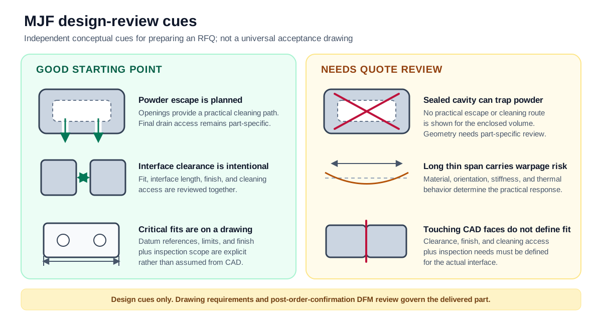
Good starting point
Powder escape, planned interface clearance, and drawings with defined datum references give the quote a defined engineering starting point.
Needs quote review
Sealed cavities, long thin spans, and touching CAD faces need part-specific review for cleaning, warpage, finish, fit, and inspection.
Ready to price the geometry?
Upload the part, drawing, quantity, and delivered-condition requirements
Standard MJF requests receive a quote response within 24 hours. DFM review begins after order confirmation.
Specify the delivered condition, not only the print process
As-printed surface, color, critical interfaces, hardware, cleaning, and inspection can change both the route and the schedule.
Review finish, machining, thread, and insert options
Depowdering and bead blasting
The baseline workflow removes loose powder and evens the as-printed matte surface.
Black dye and appearance finishing
Dyeing, painting, or smoothing can be evaluated against the exact material, supplier workflow, and appearance target.
Secondary machining
Critical datums, sealing faces, or precision holes can be reviewed for CNC finishing when geometry permits.
Threads and inserts
Tapping and heat-set or mechanical inserts can be quoted when wall thickness, access, load, and assembly sequence support them.
Use MJF where functional geometry and batch logic align
The application examples below still need grade-specific load, temperature, environment, finish, inspection, and regulatory review.
Robotics and automation
Sensor mounts, protective housings, gripper components, cable guides, end-of-arm fixtures, and low-mass brackets.
Industrial equipment
Ducts, clips, guards, manifolds, jigs, fixtures, covers, and replacement components without production tooling.
Mobility and vehicle development
Prototype ducts, brackets, housings, clips, and assembly aids with application-specific heat and load review.
Consumer hardware pilots
Pilot housings, internal frames, assembly fixtures, and functional prototypes before or alongside tooling decisions.
Bridge production and service parts
Produce qualified low-volume batches while tooling is pending, demand is developing, or a service-part program needs production without dedicated tooling.
Review material and finish notes for the illustrations above
These are not customer parts or guaranteed delivered finishes. The quote confirms the exact material, finish, inspection, and acceptance requirements.
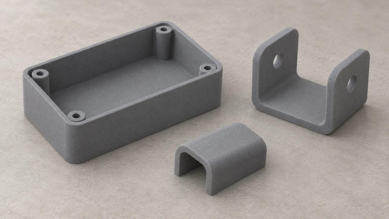
Illustration 1
- Process:
- MJF
- Material:
- PA12 Nylon-style production material
- Finish/state:
- Gray matte appearance
- Use:
- Enclosures, mounting brackets, and cable guides
Illustration 2
- Process:
- MJF
- Material:
- PA12 Nylon-style powder-bed material
- Finish/state:
- Unpacked condition before final cleaning
- Use:
- Depowdering, cleaning, and finish planning
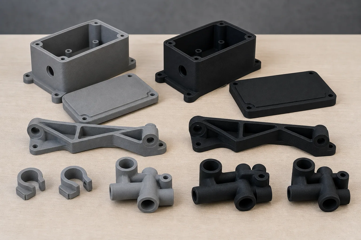
Illustration 3
- Process:
- MJF
- Material:
- PA12 Nylon-style powder-bed material
- Finish/state:
- Natural gray and black-dyed comparison
- Use:
- Housings, lids, brackets, clips, and manifolds
Choose by material, geometry, quantity, finish, and delivery risk
These processes overlap. The practical choice depends on the exact machine, grade, supplier workflow, packed build, post-processing, and inspection plan.
Open the detailed MJF, SLS, and FDM comparison
This table scrolls horizontally on smaller screens. Focus the table region and use the left and right arrow keys or swipe to review all columns.
| Decision factor | MJF | SLS | FDM |
|---|---|---|---|
| How each layer forms | Jetted fusing and detailing agents plus thermal energy | A laser traces and fuses each cross-section | A nozzle extrudes thermoplastic filament |
| Dedicated printed supports | Generally not required; powder escape still matters | Generally not required; powder escape still matters | Used when overhangs and geometry require them |
| Material decision | PA12 Nylon, PA11 Nylon, PA12 GB, and grade-specific flexible options | Supplier-specific powder portfolio can broaden the choice | Broad filament thermoplastics, including application-specific grades |
| Often worth evaluating for | Detailed functional nylon parts and packed repeat builds | Functional powder-bed parts where its material, envelope, finish, or economics fit | Sparse prototypes, large simple fixtures, or a required filament thermoplastic |
| Decision variables | Quantity, nesting, cooling, geometry, material, finish, and inspection | Quantity, packing, geometry, material, finish, and supplier system | Orientation, support, layer interfaces, material, finish, size, and quantity |
| Surface appearance | Fine matte appearance; native color depends on the approved grade and printer system. Dyeing, painting, or smoothing can be quoted | Powder-bed matte finish; color and refinement depend on material and supplier workflow | Visible layer lines are typical; sanding, coating, or machining may improve selected surfaces |
| Mechanical consistency | Comparatively uniform, but not equal in every direction; confirm the grade and application data | Functional powder-bed behavior still varies with grade, orientation, geometry, and process controls | Layer interfaces are commonly more direction-sensitive; orientation remains a primary design input |
| Production throughput | Area-wide agent jetting can suit packed repeat builds; cooling and post-processing remain schedule inputs | Laser scanning, packing, cooling, and post-processing determine the job schedule | Serial extrusion time grows with deposited material, supports, part count, and layer settings |
| Geometry freedom | Complex external and internal geometry without dedicated supports; powder escape and warpage still matter | Complex powder-bed geometry without dedicated supports; powder escape and thermal risk still matter | Broad geometry range, but overhangs, support access, bridging, and orientation can constrain the design |
| Relative cost drivers | Nesting and packed repeat builds can improve per-part cost; material, cooling, finish, and inspection still apply | Packing, powder system, material choice, finish, quantity, and supplier utilization shape cost | Sparse parts can be economical; machine time, material, supports, labor, and quantity determine the result |
Quote the delivered part
Upload CAD, drawings, quantity, finish, and inspection needs
We will review whether MJF fits the geometry and production plan, then confirm the exact material, finish, tolerance approach, inspection scope, and schedule in the quote. Standard MJF requests receive a quote response within 24 hours. DFM review begins after order confirmation.
MJF 3D printing questions
Buyer-focused answers for process selection, material review, tolerances, finishing, and qualification.
Continue the MJF process review
Compare the parent service and MJF-versus-SLS decision factors before submitting the RFQ.
Need a process recommendation before quoting?
Send the engineering context. We can compare MJF with SLS, FDM, CNC machining, or another process against the part requirements.