What Is CNC Machining?
CNC (Computer Numerical Control) machining is a subtractive manufacturing process where pre-programmed computer software controls the movement of cutting tools to remove material from a solid workpiece. This guide covers every major CNC process type: milling, turning, Swiss-type, grinding, wire EDM, and routing, along with the tolerances, trade-offs, and decision framework you need to specify the right process for your part.
Why every mechanical engineer needs to understand CNC process types
Specifying the wrong CNC process is one of the most common (and expensive) mistakes in early-career engineering. A shaft turned on a lathe costs a fraction of the same shaft milled from billet. A Swiss-type machine can produce 500 bone screws in the time a standard lathe produces 50. Wire EDM can cut a hardened D2 tool-steel die insert that would destroy conventional end mills. Understanding which process to specify, and why, directly affects your part cost, lead time, achievable tolerances, and surface finish. This guide walks through each CNC process from first principles.
What Is CNC Machining?
CNC machining is a subtractive manufacturing process where computer-controlled machine tools remove material from a solid workpiece (called “stock” or “billet”) to produce a finished part. The “CNC” stands for Computer Numerical Control. The machine follows a program (G-code) that specifies toolpaths, feed rates, spindle speeds, and depth of cut with sub-thousandth-of-an-inch repeatability.
If you are turning this definition into a supplier-ready package, use our RFQ checklist to confirm your STEP file, 2D drawing, tolerances, material callouts, and inspection notes are complete before quoting starts.
Quick Overview
Watch: CNC Machining Explained in 2 Minutes
Prefer the visual version first? This short video shows the core idea behind CNC machining before you go deeper into the process details, tolerances, and machine types below.
Subtractive, not additive
Unlike 3D printing (additive), CNC machining starts with a block of material and removes everything that is not the final part. The result is a fully dense, isotropic part with mechanical properties identical to the parent material, with no layer lines, no porosity, and no anisotropy.
G-code drives every movement
A CAM (Computer-Aided Manufacturing) program converts your 3D model into G-code, a line-by-line set of instructions that tell the machine where to move the tool, how fast to spin it, and how deep to cut. G-code is generated from CAM software (Fusion 360, Mastercam, SolidCAM, etc.) based on the 3D model and the programmer's process knowledge.
Axes define capability
On a standard VMC, a "3-axis" machine moves the table in X and Y while the spindle moves in Z. CNC programs describe the relative tool path in all three axes. A "5-axis" machine adds two rotary axes (typically A and B or B and C), allowing the tool to approach the workpiece from virtually any angle. More axes means more geometric freedom, but also higher machine cost, programming complexity, and hourly rate.
Material versatility
CNC machines can cut metals (aluminum, steel, titanium, Inconel, copper, brass), engineering plastics (PEEK, Delrin, Nylon, polycarbonate), and even composites and ceramics with the right tooling. If a material can be clamped in a vise and cut with a carbide or diamond tool, it can likely be CNC machined.
The CNC Workflow: CAD → CAM → G-code → Part
CAD Model
Engineer creates a 3D model (STEP, IGES, or native CAD format) with all dimensions, tolerances, and surface finish callouts on the 2D drawing.
CAM Programming
A CNC programmer imports the model into CAM software, selects tools, defines toolpaths, and sets feeds/speeds based on material and machine capability.
Setup & Machining
The operator loads stock material, secures it in a vise or fixture, loads the tools, verifies offsets, and runs the program. Coolant floods the cut zone to manage heat and chip evacuation.
Inspection
The finished part is measured against the drawing using calipers, micrometers, a CMM (coordinate measuring machine), or a profilometer, depending on the tolerance and surface finish requirements.
Pro Tip
Always provide both a 3D model (STEP preferred) and a 2D drawing (PDF) to your CNC supplier. The 3D model drives the CAM toolpath; the 2D drawing communicates tolerances, surface finishes, and special notes that cannot be embedded in the model. Sending only one or the other costs you time and invites errors.
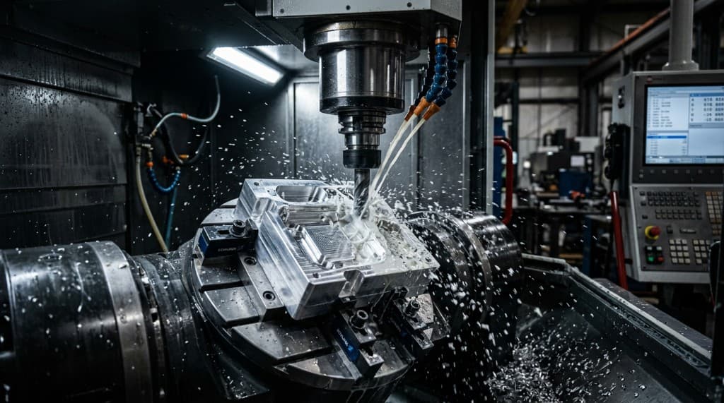
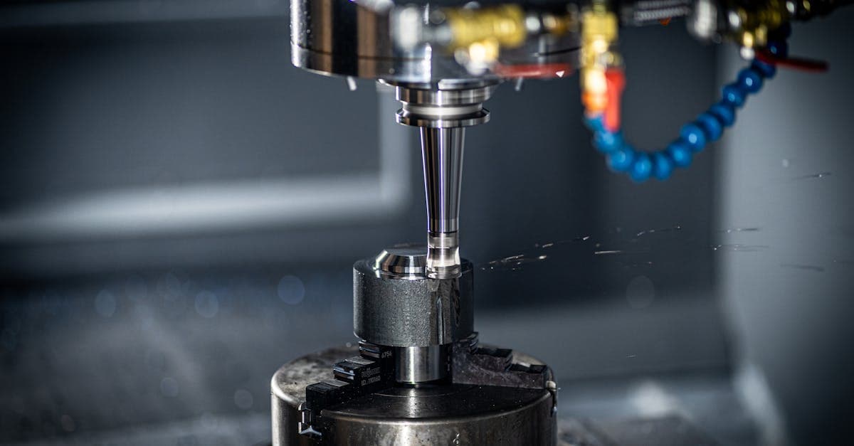
CNC Milling
CNC milling is the most versatile and widely used CNC process. A rotating multi-point cutting tool (end mill, face mill, ball nose, or drill) moves across a workpiece that is clamped to a table, removing material to create flat surfaces, pockets, slots, holes, contours, and complex 3D shapes.
3-Axis Milling
On a standard VMC, the table moves the workpiece in X (left/right) and Y (front/back) while the spindle moves in Z (up/down). CNC programs describe relative tool motion in all three axes. This handles the majority of prismatic parts, including housings, brackets, plates, and enclosures. Multiple setups (flipping the part) are needed to machine features on different faces.
4-Axis Milling
Adds one rotary axis (typically A-axis, rotating the workpiece around X). This allows the part to be indexed or continuously rotated during cutting, enabling features on multiple faces without re-fixturing. It is common for parts with features at regular angular intervals, like a cylinder with cross-holes every 90°.
5-Axis Milling
Adds two rotary axes (A + B, or B + C), allowing the tool to approach the workpiece from virtually any angle. Available as 3+2 (positional, where the rotary axes lock during cuts) or simultaneous 5-axis (all axes move concurrently). Eliminates multiple setups, improves accuracy (no re-fixturing error), and enables complex contoured surfaces such as impellers, turbine blades, and complex structural components.
Common Milling Operations
Face Milling
Creates flat surfaces using a large-diameter face mill. Typical first operation to establish a reference datum.
Pocket Milling
Removes material from an enclosed cavity. Requires attention to corner radii because internal corners will have a radius equal to the tool radius.
Contour Milling
Follows a 2D or 3D profile around the part perimeter. Used for complex outer shapes and freeform surfaces.
Drilling & Tapping
Creates through-holes and threaded holes. Specify hole diameter, depth, and thread callout (e.g., M6×1.0, #10-32 UNF) on your drawing.
Slot Milling
Cuts narrow grooves for keyways, O-ring grooves, or assembly features. Width is constrained by tool diameter.
Plunge Milling
The tool cuts axially (like a drill) rather than laterally. Used for rapid material removal in deep pockets or hard materials like Inconel 718.
Design Tip
Internal corners on milled pockets will always have a radius equal to (or larger than) the cutting tool radius. If your design requires a sharp internal corner for fit (e.g., to mate with a square boss), add a relief, which is a small circular pocket at the corner, or specify an undercut. Calling out “sharp corners” on a milled pocket is not physically achievable and will result in an RFI from the shop.
CNC Turning (Lathe)
CNC turning is the process of rotating a workpiece in a chuck or collet while a single-point cutting tool moves along its axis and radius to create cylindrical geometry. If your part is axially symmetric, such as shafts, pins, bushings, threaded studs, and nozzles, turning is almost always the primary process.
How it works
The workpiece is clamped in a rotating chuck (or collet). A cutting tool, held in a tool turret, moves in two axes: Z (along the axis of rotation) and X (radially toward/away from the center). The combination of rotation and linear tool motion generates cylindrical surfaces, tapers, grooves, threads, and faces. Modern CNC lathes have 8–12 tool turrets that index automatically between operations.
Turning vs. milling for round parts
A shaft turned on a CNC lathe is typically 3–5× less expensive than the same shaft milled from rectangular billet on a CNC mill because turning removes material far more efficiently on cylindrical geometry. The tool is in continuous contact, material removal rate is high, and setup is simpler. Always choose turning as the primary process for round parts.
Live tooling (turn-mill)
Modern CNC lathes can include "live tools," which are small milling spindles mounted in the turret that allow the machine to mill flats, cross-holes, keyways, and hex features without moving the part to a separate milling machine. This turn-mill capability reduces handling, improves concentricity, and cuts lead time. It is standard on most mid-range CNC lathes built after 2010.
Typical tolerances and surface finish
Standard CNC turning tolerance: ±0.005 in. (±0.13 mm) on diameters, ±0.010 in. (±0.25 mm) on lengths. Precision turning with fine boring: ±0.001 in. (±0.025 mm) on diameters. Surface finish: Ra 32–63 μin. (0.8–1.6 μm) standard; Ra 8–16 μin. (0.2–0.4 μm) with diamond inserts on non-ferrous materials.
Common Turning Operations
OD Turning
Reduces the outside diameter of the workpiece. This is the most basic turning operation and it creates cylinders, tapers, and stepped diameters.
Facing
Cuts a flat surface perpendicular to the axis of rotation. Establishes part length and a reference surface.
Boring
Enlarges an existing hole to a precise diameter. Achieves tighter tolerances (±0.001 in. / ±0.025 mm) than drilling alone.
Threading
Cuts external or internal threads using single-point threading or thread-milling inserts. Specify thread standard (UNC, UNF, Metric), class of fit, and length of engagement on your drawing.
Grooving / Parting
Creates narrow grooves (O-ring seats, snap-ring grooves) or cuts the finished part off the bar stock. Groove width and depth must match tooling availability.
Knurling
Imprints a diamond or straight-line pattern on the OD for grip. Specify pattern type (diamond, straight) and pitch (e.g., 21 TPI medium diamond knurl).
Pro Tip
When designing a turned part, minimize the number of diameter steps and avoid deep, narrow internal bores (L/D > 4:1 on boring operations). Deep bores require long, slender boring bars that deflect under cutting forces, degrading tolerance and surface finish. If you need a deep bore, consider specifying it with a wider tolerance and finishing with a reamer or hone.
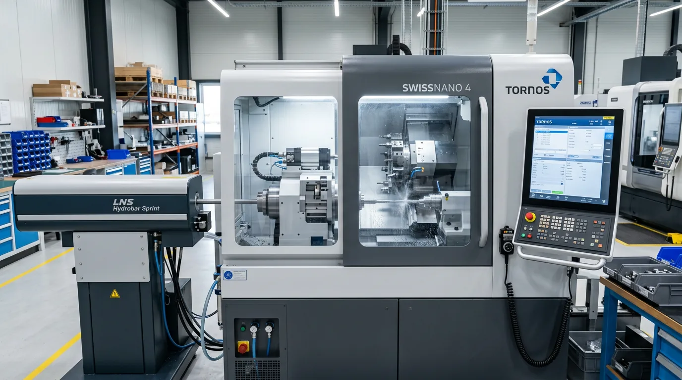
Swiss-Type CNC Machining
Swiss-type CNC (also called Swiss screw machines or Swiss-style lathes) evolved from the Swiss watchmaking industry. The defining feature is a sliding headstock with a guide bushing that supports the bar stock directly at the cutting zone, minimizing deflection on long, slender parts and enabling tolerances that standard lathes struggle to hold. For a deep comparison of Swiss vs conventional CNC turning, including L/D selection rules, tolerance tables, cost break-even analysis, and DFM rules, see our Swiss turning vs CNC turning guide.
Sliding headstock + guide bushing
In a standard CNC lathe, the workpiece extends from the chuck and the tool moves to it. The longer the overhang, the more deflection you get. In a Swiss machine, the headstock slides the bar stock through a guide bushing, so the material is always supported within 1–3 mm of the cut. This is why Swiss machines produce straight, round, concentric parts at tolerances conventional lathes cannot match on small diameters.
Ideal part profile
Swiss machining excels at parts with: small diameter (typically ≤1.25 in. / 32 mm bar capacity), high length-to-diameter ratio (L/D > 3:1, up to 12:1 or more), tight tolerances (±0.0002–0.0005 in. / ±0.005–0.013 mm), and complex features (cross-holes, flats, threads, knurls) that benefit from live tooling completed in a single cycle.
Production efficiency
Swiss machines typically run unattended from bar stock using a bar feeder. Cycle times for a typical bone screw or connector pin range from 30 seconds to 3 minutes. A single Swiss machine running two shifts can produce 500–2,000+ parts per day depending on complexity, making it highly cost-effective for medium to high volumes (100+ pieces).
Tolerances and surface finish
Swiss CNC routinely holds ±0.0005 in. (±0.013 mm) on turned diameters and ±0.0002 in. (±0.005 mm) on critical features with process optimization. Surface finish: Ra 16–32 μin. (0.4–0.8 μm) standard, with Ra 8 μin. (0.2 μm) achievable on non-ferrous materials. Thread quality per Class 3A/3B or 6g/6H is standard.
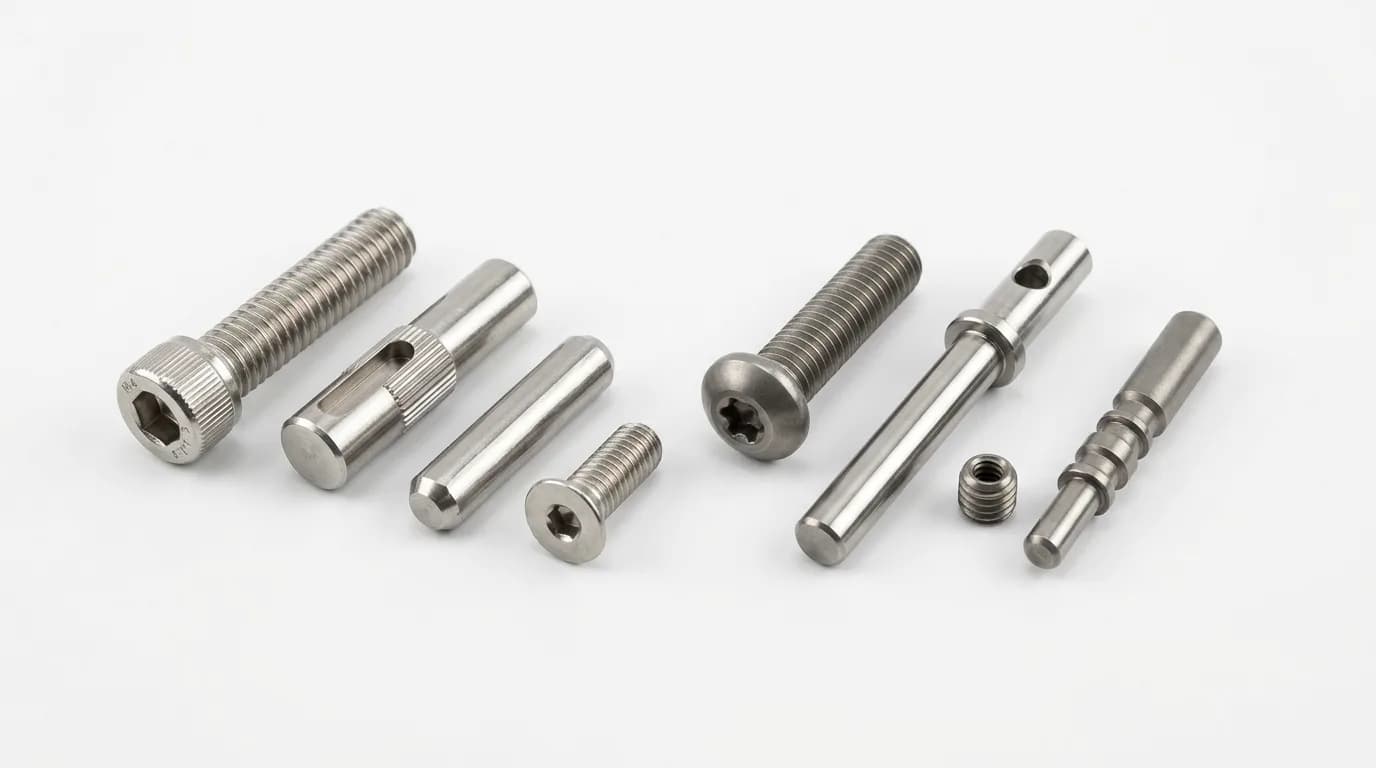
Typical Swiss-Machined Components
Pro Tip
Swiss machining hourly rates are typically $100–$175/hr vs. $75–$125/hr for a standard CNC lathe. However, the faster cycle times and tighter tolerances achieved in a single setup often make Swiss more cost-effective on a per-part basis for qualifying part geometries. Always request quotes from both Swiss and conventional lathe shops to compare total piece price, not just hourly rate.
CNC Grinding
CNC grinding uses an abrasive wheel (aluminum oxide, CBN, or diamond) to remove very small amounts of material with extreme precision. Grinding is typically a finishing process, applied after rough machining (turning or milling) to achieve tolerances and surface finishes that cutting tools alone cannot reach.
Surface grinding
A flat abrasive wheel passes over a flat workpiece held on a magnetic chuck. Produces flat surfaces with tolerances of ±0.0002 in. (±0.005 mm) and surface finishes of Ra 4–16 μin. (0.1–0.4 μm). Used for reference surfaces, gauge blocks, and die components.
Cylindrical grinding (OD/ID)
The workpiece rotates while a grinding wheel removes material from the outside diameter (OD grinding) or inside diameter (ID grinding). Achieves ±0.0001 in. (±0.0025 mm) on diameters with Ra 4–8 μin. (0.1–0.2 μm). Used for bearing journals, hydraulic spools, and precision bores.
Centerless grinding
The workpiece rests on a work rest blade between a grinding wheel and a regulating wheel, with no centers or chucks. It is ideal for high-volume production of cylindrical parts: pins, rods, shafts, and rollers. Throughfeed centerless grinding can process thousands of parts per hour with ±0.0002 in. (±0.005 mm) diameter control.
When grinding is required
Specify grinding when: (a) tolerance is tighter than ±0.001 in. (±0.025 mm), (b) surface finish must be Ra ≤16 μin. (≤0.4 μm), (c) the material is hardened (>45 HRC) and cannot be efficiently single-point turned, or (d) you need a specific geometry on hardened material (e.g., a bearing seat on a heat-treated 4340 steel shaft).
Design Tip
Leave 0.005–0.015 in. (0.13–0.38 mm) of stock on surfaces designated for grinding. This is the “grind stock”, meaning enough material for the grinding wheel to clean up the surface and reach final dimension, but not so much that grinding becomes slow and expensive. Your CNC programmer will rough-machine to near-net shape, then the grinder brings it to final tolerance.
Wire EDM (Electrical Discharge Machining)
Wire EDM uses a thin, electrically charged wire (typically brass, 0.004–0.012 in. / 0.1–0.3 mm diameter) to erode material through a series of rapid electrical discharges (sparks). The wire never touches the workpiece. material is removed by the spark energy across a small gap (0.001–0.002 in. / 0.025–0.05 mm). The process works on any electrically conductive material regardless of hardness.
No mechanical cutting forces
Because wire EDM removes material through electrical erosion rather than mechanical contact, there are zero cutting forces on the workpiece. This makes it ideal for thin-wall sections (as thin as 0.010 in. / 0.25 mm), delicate features, and hardened materials (60+ HRC) that would cause catastrophic tool wear on conventional cutters.
Tolerances and surface finish
Wire EDM routinely holds ±0.0002 in. (±0.005 mm) on profile cuts. With multiple skim passes (rough cut + 2–3 finish passes), surface finish reaches Ra 8–16 μin. (0.2–0.4 μm). Corner radii are limited by wire diameter. A 0.010 in. wire produces a minimum internal corner radius of approximately 0.005 in. (0.13 mm).
Typical applications
Stamping dies and punch tooling (hardened A2, D2, S7 tool steels), injection mold inserts, precision slots and keyways in hardened components, medical device features requiring burr-free edges, and any profile cut in materials above 45 HRC where conventional machining is impractical.
Limitations
Wire EDM is slow. Typical cutting speed is 1–10 square inches per hour (6–65 cm²/hr), making it 10–100× slower than CNC milling for bulk material removal. It requires a start hole (drilled or pre-existing) for internal cuts. It also works only on electrically conductive materials, so no ceramics, glass, or most plastics.
Pro Tip
Wire EDM leaves a thin recast layer (0.0002–0.001 in. / 0.005–0.025 mm) on the cut surface, which is a re-solidified layer that is harder and more brittle than the parent material. For fatigue-critical parts (springs, flexures), specify recast layer removal via a finishing skim pass or post-EDM polishing on your drawing.
CNC Routing
CNC routers are large-format machines designed for cutting sheet and plate materials, primarily wood, plastics, composites (carbon fiber, G10/FR4), foam, and soft metals like aluminum. While mechanically similar to CNC milling, routers are optimized for large work envelopes (4×8 ft / 1.2×2.4 m or larger), high traverse speeds, and 2D/2.5D profiling rather than tight-tolerance 3D machining.
When routing, not milling
Use CNC routing when your part is a flat or near-flat profile cut from sheet stock (plastics, composites, wood, aluminum sheet up to ~0.5 in. / 12.7 mm), the work envelope exceeds typical CNC mill table size, or the geometry is 2D/2.5D (profile cuts, pockets, holes) rather than complex 3D surfaces.
Typical tolerances and materials
CNC routers hold ±0.005–0.010 in. (±0.13–0.25 mm) on profile dimensions, which is adequate for most panel, enclosure, and fixture applications but not for precision-fit features. Common materials: HDPE, acrylic, polycarbonate, ABS, Delrin sheet, G10/FR4, carbon fiber plate, MDF, plywood, and 6061-T6 aluminum sheet.
Composites and carbon fiber
CNC routing is the standard process for trimming and profiling carbon fiber and fiberglass composite panels. Diamond-coated or PCD (polycrystalline diamond) router bits are used to prevent delamination and fiber pullout. Dust extraction is critical because carbon fiber dust is conductive and abrasive.
Cost advantages
CNC routing is typically 30–50% less expensive than CNC milling for suitable parts because router machines have lower hourly rates ($40–$80/hr vs. $75–$150/hr for a VMC), faster traversal speeds, and simpler fixturing (vacuum table or mechanical clamps on sheet stock). For panels, brackets, and covers cut from sheet material, always consider routing first.
CNC Process Comparison Table
Side-by-side comparison of all six CNC process types covered in this guide. Use this table to quickly narrow down which process fits your part geometry, tolerance, and volume requirements.
| Process | Geometry | Standard Tolerance | Achievable Tolerance | Surface Finish (Ra) | Typical $/hr | Typical Use |
|---|---|---|---|---|---|---|
| 3-Axis Milling | Prismatic, flat faces, pockets | ±0.005 in. (±0.13 mm) | ±0.002 in. (±0.05 mm) | 63–125 μin. (1.6–3.2 μm) | $75–$125 | Brackets, housings, plates |
| 5-Axis Milling | Complex 3D, undercuts, contours | ±0.003 in. (±0.08 mm) | ±0.001 in. (±0.025 mm) | 16–63 μin. (0.4–1.6 μm) | $125–$200 | Impellers, robotics structures, medical |
| CNC Turning | Cylindrical, axially symmetric | ±0.005 in. (±0.13 mm) | ±0.001 in. (±0.025 mm) | 32–63 μin. (0.8–1.6 μm) | $75–$125 | Shafts, bushings, fittings |
| Swiss-Type CNC | Small Ø, high L/D, complex | ±0.0005 in. (±0.013 mm) | ±0.0002 in. (±0.005 mm) | 16–32 μin. (0.4–0.8 μm) | $100–$175 | Bone screws, pins, fasteners |
| CNC Grinding | Flat or cylindrical surfaces | ±0.0002 in. (±0.005 mm) | ±0.0001 in. (±0.0025 mm) | 4–16 μin. (0.1–0.4 μm) | $80–$150 | Bearing journals, die inserts, gauges |
| Wire EDM | 2D profiles in conductive materials | ±0.0005 in. (±0.013 mm) | ±0.0002 in. (±0.005 mm) | 8–32 μin. (0.2–0.8 μm) | $75–$150 | Dies, mold inserts, hardened parts |
| CNC Routing | 2D/2.5D sheet profiles | ±0.005–0.010 in. (±0.13–0.25 mm) | ±0.003 in. (±0.08 mm) | 63–250 μin. (1.6–6.3 μm) | $40–$80 | Panels, covers, composite trim |
Note on Tolerances
All tolerances listed are general guidelines for common materials (6061-T6 aluminum, 303/304 stainless steel) under standard shop conditions. Actual achievable tolerances depend on specific material, feature geometry (wall thickness, depth-to-width ratio), machine condition, and fixturing. Always confirm tolerance capabilities with your specific supplier for critical dimensions.
How to Choose the Right CNC Process
Use this decision framework to match your part requirements to the correct CNC process. Start with the geometry, then consider tolerance, material hardness, and volume.
Is the part axially symmetric (round)?
CNC Turning is your primary process. Add live tooling for cross-features, or secondary milling for non-round features.
CNC Milling is your primary process. Choose axis count based on geometric complexity.
Is the diameter ≤1.25 in. (≤31.8 mm) with L/D > 3:1?
Swiss-Type CNC, especially if volume is 100+ pieces and tight tolerances (±0.0005 in. / ±0.013 mm) are required.
Standard CNC Turning for larger diameters or short parts.
Does the part have complex 3D contours or undercuts?
5-Axis Milling (simultaneous) for continuous contoured surfaces. 3+2 Milling if the features are on discrete angular faces.
3-Axis Milling for prismatic geometry because it offers lower cost and simpler programming.
Is the material hardened (>45 HRC)?
Wire EDM for profile cuts and complex shapes. CNC Grinding for cylindrical or flat surfaces. Hard milling with CBN tools as a third option for shallow features.
Standard CNC milling or turning with carbide tooling.
Do you need a tolerance tighter than ±0.001 in. (±0.025 mm)?
CNC Grinding (flat or cylindrical surfaces), or Swiss CNC (small diameters). Wire EDM for profile tolerances. Consider adding a finish grinding operation after rough CNC machining.
Standard CNC milling or turning is sufficient, with no secondary finishing process required.
Is the part a flat profile from sheet stock?
CNC Routing for lower cost and faster traversal, especially for plastics, composites, and thin aluminum sheet. Consider laser or waterjet cutting as alternatives.
CNC Milling from billet is appropriate for 3D geometry from solid stock.
Pro Tip
Most production parts use more than one CNC process. A typical precision shaft might be: (1) bar-fed turned on a CNC lathe for OD profile, (2) milled for cross-holes and keyways via live tooling or a second-op mill, and (3) centerless ground on the bearing journals to final diameter and finish. When designing, think about the process sequence , not just the single machine that makes the part.
Key Takeaways
CNC machining is not one process. It is a family of subtractive processes, each optimized for a specific geometry, tolerance range, and material condition. Choosing the right process (or combination of processes) for your part directly affects cost, lead time, achievable quality, and your supplier's ability to deliver consistently.
Geometry First
Round parts → turning. Prismatic parts → milling. Small-diameter + tight-tolerance → Swiss. Hardened materials → grinding or wire EDM. Sheet profiles → routing.
Tolerance Drives Cost
Specify tight tolerances (±0.001 in. / ±0.025 mm or tighter) only on functionally critical features. Every dimension that is tighter than standard (±0.005 in. / ±0.13 mm) adds cost through tooling, inspection time, and reject rate.
Combine Processes
Most production parts use 2–3 processes in sequence: rough mill → finish mill → grind, or turn → mill (live tooling) → EDM. Design with the full process chain in mind.
Further Reading
Frequently Asked Questions
What is the difference between CNC milling and CNC turning?
When should I use Swiss-type CNC instead of a standard lathe?
What tolerances can CNC machining achieve?
What materials can be CNC machined?
How does wire EDM differ from conventional CNC machining?
What is 3+2 machining and how does it differ from full 5-axis?
How do I decide between CNC machining and 3D printing?
What surface finishes are achievable with CNC machining?
Related Resources
Ready to Get Your Parts CNC Machined?
Upload your CAD file and 2D drawing. MakerStage provides detailed quotes with process recommendations, tolerances, and lead times for milling, turning, and more.
Get CNC Quote