The Complete Guide to 3D Printing
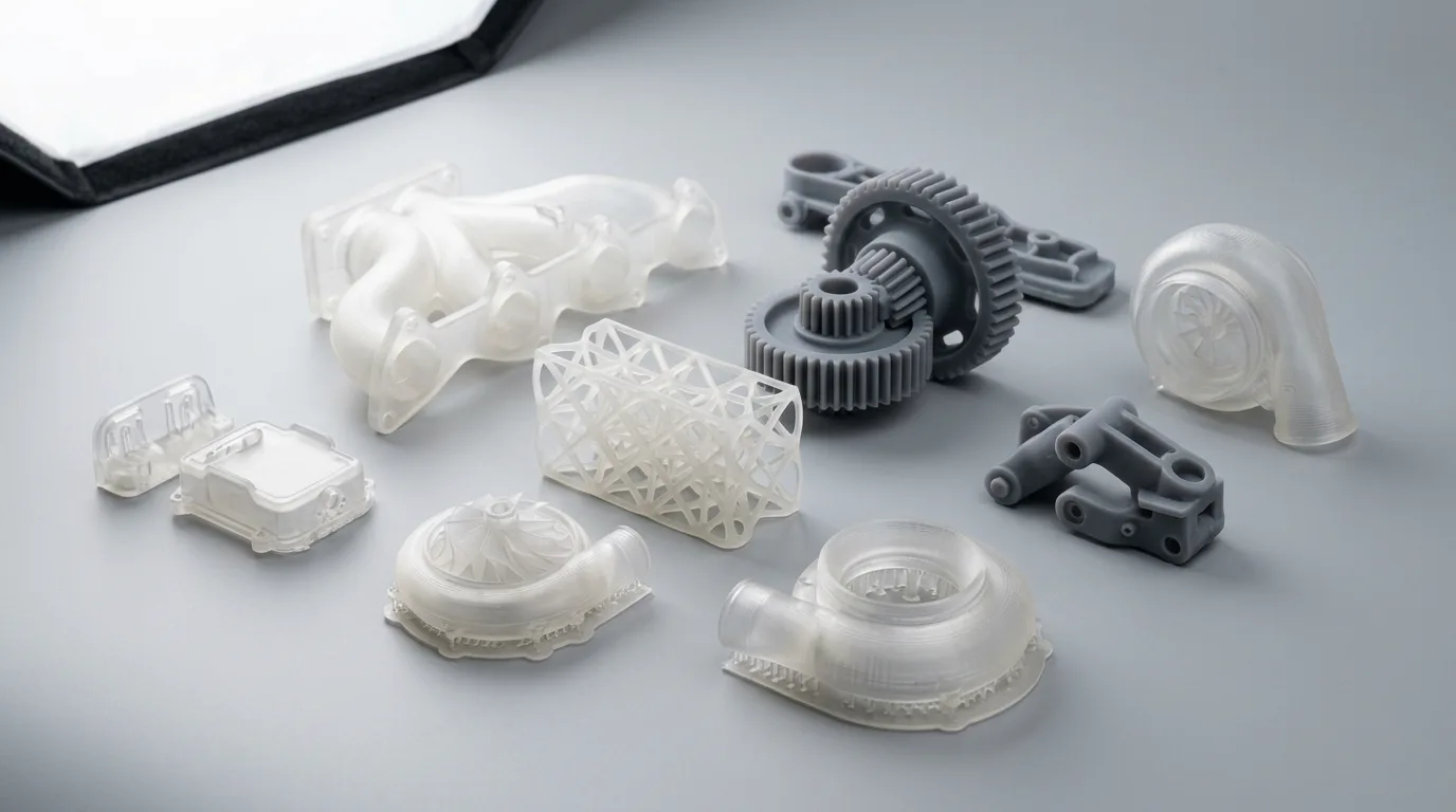
3D printing (additive manufacturing) builds parts layer by layer from digital CAD files. Seven commercially relevant processes — FDM, SLA, DLP, SLS, MJF, DMLS/SLM, and Metal FFF — span polymers and metals, with tolerances from ±0.05 mm (±0.002 in.) for SLA to ±0.5 mm (±0.02 in.) for FDM, and per-part costs from $5 (FDM prototype) to $2,000+ (DMLS titanium). This guide covers all of them.

What's Inside This Guide
What Is 3D Printing?
3D printing — formally additive manufacturing (AM) — is any process that builds a three-dimensional object by depositing material layer by layer, guided by a digital model (typically an STL or 3MF file sliced into 2D cross-sections). Unlike CNC machining (subtractive) or injection molding (formative), AM adds material only where needed, which enables geometries impossible to achieve with traditional methods: internal channels, lattice structures, topology-optimised lightweighting, and consolidated assemblies.
The seven commercially relevant AM processes fall into three families:
- Extrusion-based (FDM): Melts and deposits thermoplastic filament through a heated nozzle.
- Photopolymerisation (SLA, DLP): Uses UV light to selectively cure liquid resin.
- Powder-based (SLS, MJF, DMLS/SLM, Binder Jetting): Selectively fuses or binds particles in a powder bed.
- Metal extrusion (Metal FFF): Extrudes metal-polymer composite filament, then debinds and sinters to full density.

For a detailed breakdown of each technology's physics, trade-offs, and real cost data, read our Types of 3D Printing: Complete Technology Comparison.
All 7 Technologies at a Glance
Side-by-side comparison of tolerance, resolution, surface finish, and cost across every commercial AM process. *Cost ranges are for typical small-to-medium parts (50–200 cm³).
| Process | Typical Tolerance | Layer Height | Min Feature | Surface Finish (Ra) | Cost per Part* |
|---|---|---|---|---|---|
| FDM | ±0.5 mm | 100–400 µm | 0.8 mm | 10–25 µm | $3–$50 |
| SLA | ±0.05–0.13 mm | 25–100 µm | 0.2 mm | 1–3 µm | $15–$80 |
| DLP | ±0.05–0.10 mm | 25–100 µm | 0.3 mm | 1–4 µm | $8–$60 |
| SLS | ±0.25 mm | 60–120 µm | 0.7 mm | 6–15 µm | $30–$80 |
| MJF | ±0.20 mm | 80 µm | 0.5 mm | 5–10 µm | $25–$65 |
| DMLS/SLM | ±0.10 mm | 20–60 µm | 0.4 mm | 6–20 µm | $150–$500 |
| Metal FFF | ±0.5 mm → ±1% | 100–200 µm | 1.0 mm | 8–20 µm | $50–$500 |

For detailed cost breakdowns, material properties, and DFM guidelines per technology, see the deep-dive chapters below.
Polymer 3D Printing Technologies
Four processes cover 90%+ of polymer AM applications — from $200 desktop prototyping to $500k production lines.
FDM — Fused Deposition Modeling
The workhorse of desktop and industrial prototyping. FDM melts thermoplastic filament through a heated nozzle, tracing each layer's cross-section. It offers the widest material range of any polymer AM process — from commodity PLA to high-performance PEEK — and the largest build volumes (up to 914 × 610 × 914 mm on Stratasys F900). Trade-off: visible layer lines and anisotropic mechanical properties.
SLA — Stereolithography
A UV laser (405 nm) traces each cross-section on a vat of liquid photopolymer resin, curing it layer by layer. SLA delivers the best surface finish of any polymer AM process — layer lines are nearly invisible at 25 µm resolution. Modern desktop SLA uses inverted (bottom-up) architecture. Trade-off: most resins are brittle and degrade under prolonged UV exposure.
SLS — Selective Laser Sintering
A CO₂ laser selectively sinters nylon powder layer by layer. No supports needed — unsintered powder acts as its own support, enabling complex geometries (internal channels, interlocking assemblies). SLS parts are near-isotropic and approach injection-molded strength in PA12. It's the dominant process for functional polymer production parts.
MJF — HP Multi Jet Fusion
HP's proprietary powder-bed process jets fusing and detailing agents onto nylon powder, then fuses each layer with an IR lamp. Build time depends on Z-height, not part count — filling the build plate doesn't increase print time. MJF delivers near-isotropic properties with finer detail than SLS (600 dpi XY resolution). Lower per-part cost than SLS at volume.
Metal 3D Printing Technologies
Two pathways to metal additive parts — laser powder bed (DMLS/SLM) for production density, and bound metal deposition (Metal FFF) for accessible cost.

DMLS/SLM — Direct Metal Laser Sintering
A high-power laser (200–1,000 W) fully melts metal powder in an inert-gas-shielded chamber (argon for most alloys, nitrogen for steels). DMLS produces fully dense (>99.5%) metal parts with mechanical properties that meet or exceed wrought equivalents after HIP treatment. Requires extensive supports (anchors to build plate, manages thermal stress) and post-processing (stress relief, wire EDM removal, CNC finishing of critical surfaces).
Metal FFF — Bound Metal Deposition
Metal FFF (Desktop Metal, Markforged Metal X) extrudes a metal-polymer composite filament, then debinds and sinters the "green" part into a fully metal component. The process prints in a standard office environment — no inert gas chamber, no loose metal powder. Parts shrink ~16–20% during sintering. Metal FFF costs 5–10× less than DMLS for comparable geometries, but tolerance and density (96–99%) are lower.
How to Choose the Right 3D Printing Process
Start with your requirements — surface finish, mechanical properties, production volume, and budget — then use this decision matrix.
| Scenario | Recommended | Why |
|---|---|---|
| Lowest-cost prototype option (visual only) | FDM | Lowest cost, largest build volume, widest desktop availability |
| Best surface finish / fine detail | SLA or DLP | 25 µm layers, near-injection-mold surface quality |
| Functional nylon parts (snap-fits, hinges) | SLS or MJF | No supports, near-isotropic PA12/PA11, production-grade strength |
| Production batch (100–10,000 nylon parts) | MJF | Build time independent of part count, lowest per-part cost at volume |
| Fully dense metal parts (robotics, medical) | DMLS/SLM | 99.5%+ density, Ti-6Al-4V / Inconel, meets ASTM standards after HIP |
| Metal prototypes (office-safe, lower cost) | Metal FFF | 5–10× cheaper than DMLS, no loose powder, good for tooling & prototypes |
| 3D Printing not ideal — tight tolerances on simple geometry | CNC Machining | ±0.025 mm, superior surface finish, wider material range for metals |
For the full decision tree with cost crossover tables and material-specific recommendations, see our Types of 3D Printing comparison.
3D Printing vs CNC Machining
These aren't competing technologies — they're complementary. The decision comes down to geometry complexity, tolerance requirements, volume, and material.
Choose 3D Printing When:
- Complex geometry (internal channels, lattices, undercuts)
- Low volumes (1–500 parts) where tooling cost can't be amortised
- Rapid iteration — design changes without retooling
- Topology-optimised or weight-reduced structures
- Consolidated assemblies (reduce part count)
Choose CNC Machining When:
- Tight tolerances needed (±0.025 mm vs ±0.05–0.5 mm for AM)
- Superior surface finish (Ra 0.4–1.6 µm vs 1–25 µm for AM)
- Specific metal alloys not available in AM powder form
- Production volumes >50 identical metal parts
- Material certifications required (mill certs, traceability)
The Hybrid Approach
Many teams use both: 3D print for prototyping and design validation, then CNC machine the production version for tighter tolerances and better surface finish. This gives you the speed of AM and the precision of subtractive manufacturing.

For detailed cost crossover analysis, tolerance comparison tables, and material compatibility charts, read our full 3D Printing vs CNC Machining article.
3D Printing Materials by Process
The process determines your available material universe. Here are the most common materials for each technology.
FDM
- PLA — prototyping, low cost
- ABS — functional, heat-resistant
- PETG — chemical resistant, food-safe
- Nylon (PA6/PA12) — tough, flexible
- PC — high impact, transparent
- PEEK (~482 °F / 250 °C HDT) / PEI (~392–423 °F / 200–217 °C HDT) — high-performance thermoplastics
SLA / DLP
- Standard resin — visual prototypes
- Tough resin — ABS-like impact
- Flexible resin — 50–80 Shore A
- High-Temp resin — HDT 460 °F / 238 °C
- Dental/castable resin — investment casting
SLS / MJF
- PA12 — workhorse nylon, ~48 MPa
- PA11 — bio-based, more ductile
- Glass-filled PA — higher stiffness
- Carbon-filled PA — ~80 MPa, lightweight
- TPU — flexible, elastomeric
- PP (MJF) — chemical resistant
DMLS / SLM
- Ti-6Al-4V — robotics, medical
- Inconel 718/625 — high-temp turbines
- 316L SS — corrosion resistant
- AlSi10Mg — lightweight structures
- 17-4 PH — hardened tooling
- Maraging steel — mold inserts
Metal FFF
- 17-4 PH — general purpose
- 316L SS — corrosion resistant
- H13 tool steel — injection mold inserts
- Ti-6Al-4V — medical, robotics
- Copper — thermal management
For full property tables (tensile strength, elongation, HDT, density) and process-specific material guides, visit our Materials Library or the Material Selection Guide.
Design for 3D Printing (DFM)
Designing for AM is different from designing for CNC or injection molding. These six rules apply across all processes.
Minimum wall thickness
FDM ≥1.2 mm, SLA ≥0.6 mm, SLS/MJF ≥0.8 mm, DMLS ≥0.4 mm. Thinner walls risk warping or incomplete fusion.
Orientation matters
All 3D printing processes are anisotropic to some degree. Z-axis (inter-layer) strength is 20–60% lower than XY for FDM; 5–15% lower for SLS/MJF. Orient critical load paths in the XY plane.
Support strategy
FDM and SLA/DLP require supports for overhangs >45°. SLS and MJF are self-supporting (unsintered powder). DMLS requires extensive metal supports to manage thermal stress.
Holes and clearances
Design holes ≥0.5 mm (SLA), ≥1.0 mm (FDM/SLS/MJF), ≥0.4 mm (DMLS). For press-fit tolerance, add +0.1 mm to nominal diameter and verify with test coupons.
Escape holes for powder processes
SLS, MJF, and DMLS require escape holes (≥4 mm diameter) for enclosed hollow sections. Without them, trapped powder adds weight and can't be removed post-build.
Shrinkage compensation
SLS parts shrink ~3.0–3.5%. MJF ~2.7%. Metal FFF ~16–20% during sintering. DMLS ~0.05–0.1%. Your service provider should compensate in slicing, but verify on first articles.
Frequently Asked Questions
Explore Every 3D Printing Guide
Deep-dive into each technology, or compare 3D printing to CNC machining.
Ready to 3D Print Your Parts?
Upload your CAD file to get engineer-reviewed pricing typically within one business day. FDM, SLA, SLS, MJF, and DMLS options can be reviewed for geometry, support, and finish risks before production.