How to Read Engineering Drawings
An engineering drawing is the contract between design, sourcing, and manufacturing. It defines dimensions and tolerances, material, surface finish, GD&T callouts, and inspection notes. This guide teaches you to read every element of a 2D drawing — from the title block to feature control frames — so you can review, approve, quote, and release drawings with confidence.
Why this is the #1 skill gap for new mechanical engineers
CAD software generates 3D models, but manufacturing still runs on 2D drawings. The drawing is what the machinist reads, what the inspector measures against, and what your supplier quotes from. If you cannot read a drawing, you cannot review a supplier's work, catch errors before production, or communicate changes. Every week spent learning CAD without learning drawing interpretation is a week of building a skill on an incomplete foundation.
Why Engineering Drawings Still Matter
A 3D CAD model defines geometry. An engineering drawing defines everything else: tolerances, material, surface finish, heat treatment, plating, inspection requirements, and special manufacturing notes. Without a drawing, a 3D model is just a shape with no quality requirements.
The drawing is the legal spec
When a dispute arises about whether a part is in tolerance, the drawing is the arbiter — not the 3D model, not an email, not a verbal conversation. Quality systems (ISO 9001, ISO 13485) treat the drawing as the binding specification. This is why every dimension, tolerance, and note matters.
Standard 3D models do not always carry all information
A standard STEP file mainly carries geometry. In many real-world RFQ workflows, it does not reliably carry the tolerances, surface finish callouts, material specifications, heat treatment instructions, plating or coating requirements, inspection levels, thread details, and manufacturing notes a shop needs to quote and make the part correctly. A 2D engineering drawing or a fully annotated model with PMI communicates that information clearly.
The drawing communicates design intent
A hole might be dimensioned from the left edge or from a datum hole. The choice tells the shop which relationship matters — and drives how the part is fixtured, machined, and inspected. Without a drawing, the programmer guesses at design intent, and guesses produce wrong parts.
Drawings enable quality control
Incoming inspection measures parts against the drawing. First article inspection (FAI) maps every dimension on the drawing to a measured value. Without a drawing, there is nothing to inspect against — the shop declares the part "good" and you have no basis to reject it if it does not fit.
The Title Block
The title block is the first thing to read on any drawing. It is located in the lower-right corner and contains the metadata that tells you what the drawing is, who owns it, and what rules apply.
| Field | What It Contains | Why It Matters |
|---|---|---|
| Part Number | Unique identifier (e.g., MS-2026-0041) | How you order, track, and reference the part. Must match the PO. |
| Part Name | Descriptive name (e.g., "Motor Mount Bracket") | Identifies the part visually — the number is the formal reference. |
| Revision | Letter (A, B, C…) or number | Ensures you manufacture to the correct version. Rev mismatches = wrong parts. |
| Material | Alloy/grade and condition (e.g., "6061-T6 Aluminum") | Defines raw material. Missing = RFI. Wrong = scrapped lot. |
| Finish | Coating/treatment (e.g., "Type II Anodize, Black") | Specifies surface treatment after machining. |
| Scale | Drawing scale (e.g., 1:1, 2:1, 1:2) | Do NOT measure directly from the paper/PDF. Use dimensions only. |
| Units | Inch or millimeter | Check this before reading any dimension. Mixing units = catastrophic errors. |
| Projection | Third-angle (US) or first-angle (EU) symbol | Determines how views are arranged. Misreading this inverts all features. |
| Tolerance Block | "Unless Otherwise Specified" default tolerances | Any dimension without an explicit tolerance uses these defaults. |
| Drawn / Checked / Approved | Names, signatures, dates | Establishes who is responsible. Required for regulated industries. |
| Dimensioning / GD&T Standard | "Per ASME Y14.5-2018" or ISO GPS standards such as ISO 1101, ISO 128, and ISO 5456-2 | Defines how dimensions, GD&T callouts, and view conventions are interpreted. Different standards can change how a drawing is read. |

Projection Methods
Projection method determines how 3D geometry is represented in 2D views. Getting this wrong means every feature you read from the drawing will be on the wrong side of the part.
Third-Angle Projection (US Standard)
The standard in the US, Canada, and most of Asia per ASME Y14.3. Views are placed as if looking through the part: the top view is above the front view, the right view is to the right. This matches intuition — "what you see is where it goes." Symbol: a truncated cone with the small end toward you, shown in the title block.
First-Angle Projection (ISO/European Standard)
The standard on many European drawings, based on ISO projection conventions such as ISO 5456-2. Views are arranged as if the part were projected through the plane: the top view is below the front view, and the right-side view is placed to the left. If you see the first-angle projection symbol in the title block, flip your normal US view-reading habit before interpreting the part.
Rule of thumb
If the drawing comes from a US or Canadian company, assume third-angle unless the symbol says otherwise. If it comes from a European company, check the symbol. When in doubt, look at a simple feature (like a through-hole) and verify which view it appears in. If it matches your expectation, you have the right projection. If it seems flipped, switch your mental model.
Types of Dimensions
Dimensions tell the manufacturer the size, location, and geometry of every feature. Each type communicates a different kind of information.
Linear Dimensions
Distance between two points, surfaces, or features. Shown as a number with extension lines and arrows. The most common dimension type — length, width, height, hole depth, wall thickness.
Diameter (⌀)
The ⌀ symbol before a number indicates a diameter. "⌀0.500 ±0.005" means a cylindrical feature with 0.500 in. (12.70 mm) nominal diameter and ±0.005 in. (±0.13 mm) tolerance. Always used for holes, pins, bores, and shafts.
Radius (R)
"R" before a number indicates a radius. "R0.125" means a 0.125 in. (3.18 mm) radius on a fillet or corner. The center of the radius is implied or shown with a small cross.
Angular Dimensions
An angle between two surfaces or features, shown in degrees. "45° ±1°" means the angle is 45 degrees with a ±1-degree tolerance. Used for chamfers, angled faces, and V-grooves.
Thread Callouts
Thread specifications follow a standard format: "M6×1.0-6H" (metric) or "1/4-20 UNC-2B" (inch). The callout specifies nominal size, pitch, thread standard, and class of fit. Always include thread depth or length of engagement.
Reference Dimensions
Dimensions in parentheses — e.g., "(2.500)" — are reference (informational) only and are not inspected. They are derived from other dimensions and provided for convenience. Never manufacture to a reference dimension.
Basic Dimensions
Dimensions in a rectangle — e.g., [1.000] — are theoretically exact and have zero tolerance. They define the true position of features in GD&T callouts. The tolerance comes from the feature control frame, not the basic dimension.
Chamfer Callouts
Chamfers are dimensioned as depth × angle: "0.030 × 45°" or as two legs: "0.030 × 0.030." Standard 45° chamfers on sharp edges are often called out in the general notes: "BREAK ALL SHARP EDGES 0.005–0.015."
Counterbore / Countersink
Counterbore (⌴): a flat-bottomed recess for a socket head cap screw. Countersink (⌵): a conical recess for a flat-head screw. Callout includes diameter and depth (cbore) or diameter and angle (csink).
Understanding Tolerances on a Drawing
Every dimension has a tolerance — the permissible variation from nominal. Tolerances determine whether a part passes or fails inspection and directly drive manufacturing cost.
Block tolerances (title block defaults)
The "Unless Otherwise Specified" note in the title block establishes default tolerances. Example: "±0.005 in. (±0.13 mm) for 2-place decimals, ±0.010 in. (±0.25 mm) for 1-place decimals, ±0.5° for angles." Any dimension without an explicit tolerance uses these values. These are the most economical tolerances because they match standard shop capability.
Bilateral tolerances (±)
The dimension includes equal variation in both directions: "1.500 ±0.005" means 1.495 to 1.505 in. (37.97 to 38.23 mm) is acceptable. This is the most common explicit tolerance format on CNC drawings.
Unilateral tolerances (+0.005/−0.000)
The tolerance is applied in one direction only: "1.500 +0.005/−0.000" means 1.500 to 1.505 in. (38.10 to 38.23 mm). Used for press-fit holes, interference fits, and features where one direction of deviation is acceptable but the other is not.
Limits of size (1.495–1.505)
Instead of nominal ± tolerance, the drawing shows the acceptable range directly. "1.495–1.505" means any value in that range passes. Functionally identical to "1.500 ±0.005" but leaves no room for arithmetic error. Common on critical features.

Cost rule of thumb
Tighter tolerances usually increase machining and inspection cost, but the impact depends on material, feature geometry, machine capability, and the inspection plan. As a practical guide, ±0.010 in. (±0.25 mm) is standard shop work, ±0.005 in. (±0.13 mm) often requires more careful setup, ±0.001 in. (±0.025 mm) usually needs tighter process control and better inspection, and ±0.0005 in. (±0.013 mm) may require specialty methods on selected features. Specify tight tolerances only where function demands them — and use the CNC Tolerances Guide for detailed cost impact data.
Surface Finish Symbols
Surface finish controls the roughness of a machined surface, usually called out as Ra (arithmetic mean roughness). On modern ISO references, Ra terminology is covered by ISO 21920, while many shops and legacy drawings still reference ISO 4287. The surface finish symbol on an engineering drawing is a checkmark-like mark with a value showing the required maximum roughness in microinches (μin.) or micrometers (μm).
| Ra (μin.) | Ra (μm) | Process | Typical Application |
|---|---|---|---|
| 250 | 6.3 | Rough machining, sawing | Non-functional surfaces, hidden faces |
| 125 | 3.2 | Standard milling | General-purpose surfaces, as-machined default |
| 63 | 1.6 | Fine milling, standard turning | Mating surfaces, bearing housings (rough) |
| 32 | 0.8 | Fine turning, finish milling | Sealing surfaces, O-ring grooves, bearing bores |
| 16 | 0.4 | Grinding, fine boring | Precision bearing journals, hydraulic bores |
| 8 | 0.2 | Lapping, honing, polishing | Optical surfaces, precision gauge faces |
| 4 | 0.1 | Superfinishing, electropolishing | Medical implant surfaces, mirror finish |
GD&T on a Drawing (Quick Primer)
GD&T callouts appear as rectangular feature control frames attached to features via leader lines. If you see these on a drawing and need a deep understanding, read our full GD&T Guide. If you specifically need help decoding compartment order, modifiers, and datum references, use the feature control frame guide. Here is what to look for at a high level.

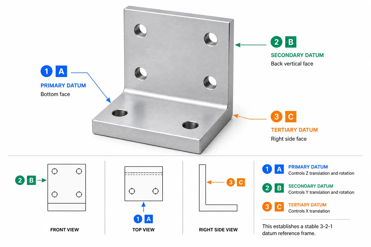
Datum flags
Triangle symbols (▼) attached to surfaces, edges, or features labeled A, B, C. These are the reference points for all GD&T measurements. Check that datum features are stable, accessible, and match the part's mounting condition.
Feature control frames
Rectangular boxes containing: [symbol | tolerance | datum references]. Read left to right. The symbol tells you the type of control (position, flatness, etc.), the number is the tolerance, and the letters are the datum references.
Position callouts on holes
The most common GD&T callout you will encounter. Defines the true location of a hole pattern relative to datums. Basic (boxed) dimensions define the nominal locations; the position tolerance defines how far each hole can deviate from true position.
Flatness on mounting faces
A flatness callout on a mounting surface ensures the surface does not bow, twist, or warp beyond the specified tolerance. Common on mating faces where a gasket or seal must seat evenly.
Perpendicularity on bores
Ensures a bore axis is square to a datum face. Critical for bearing housings, dowel pin holes, and any feature that mates with a perpendicular assembly surface.
Material condition modifiers (Ⓜ Ⓛ)
Ⓜ = MMC (bonus tolerance as feature departs from max material). Ⓛ = LMC (bonus as feature departs from least material). No modifier = RFS (tolerance applies at any size). These affect how much the position tolerance "grows" as the feature size varies.
Views, Sections & Details
A single view cannot show all features. Drawings use multiple view types to fully communicate 3D geometry on a 2D sheet.
Orthographic Views
Standard front, top, right (and sometimes left, bottom, back) views that show the part from each principal direction. Most drawings use 2–3 orthographic views.
Isometric / 3D View
A pictorial view (usually top-right) that helps visualize the part. Not dimensioned — provided for reference only to help the reader understand the 3D shape from the 2D views.
Section View (A-A)
Shows the part cut along a plane to reveal internal features. Cross-hatching fills solid areas. Labeled "SECTION A-A" with the cutting plane shown in the parent view.
Detail View
A magnified view of a small area. A circle on the parent view indicates the area, labeled with a letter. The detail view shows the same area at 2×, 4×, or higher magnification with dimensions.
Auxiliary View
A view projected from an angled surface to show its true shape. Used when a feature is on a surface that is not parallel to any standard projection plane — the auxiliary view eliminates foreshortening.
Broken / Partial View
A view where part of the geometry is omitted (shown with a jagged break line) to save space or focus attention on a specific area. Common for long shafts or repetitive patterns.
Notes, Bill of Materials & Revision Table
The notes section contains manufacturing instructions that cannot be expressed through dimensions alone. Read every note before quoting or manufacturing — missing a note is one of the top causes of nonconforming parts.
General notes
Appear in a numbered list, typically upper-left or above the title block. Cover: default tolerances, material spec, finish, deburr requirements, marking, inspection level, applicable standards (ASME Y14.5, AWS D1.1 for welding, etc.), and any restrictions ("DO NOT SCALE DRAWING").
Flag notes (local notes)
Tied to specific features via leader lines and numbered flags (e.g., ①②③). Example: "① PRESS FIT PER CLS-M4-2 FROM THIS SIDE" on a PEM insert location. Flag notes override general notes when they conflict.
Bill of Materials (BOM)
For assemblies, the BOM lists every component: item number, part number, description, quantity, and material. Each component in the assembly view is identified by a balloon number that maps to the BOM row. The BOM is the master list of what to procure and assemble.
Revision table
Tracks every change since initial release: revision letter, description, date, and approver. Always check the current revision before manufacturing. If your file says Rev B and the supplier has Rev D, request the latest — two revisions can change critical features.
Related Manufacturing References
If you are reading a drawing for quoting, machining, or inspection, these guides cover the next decisions: process capability, tolerances, GD&T interpretation, inspection, and material selection.
CNC Machining
Process capability, part types, and shop expectations.
Materials Library
Check alloys, plastics, and material callout context.
CNC Tolerances Guide
How tolerance choices affect cost and manufacturability.
GD&T Guide
Deeper explanation of feature control frames and datums.
Inspection Processes
How drawings translate into measurement and acceptance.
Frequently Asked Questions
Related Resources
Have a Drawing Ready?
Upload your engineering drawing and 3D model. MakerStage provides engineer-reviewed pricing first, with free DFM after order confirmation.
Get Free Quote Fast