Solar Mounting Materials for utility-scale hardware
A materials engineering guide for utility-scale BOS mounting hardware — galvanized carbon steel, aluminum alloys, and stainless steel compared with real property data, UL 2703 compliance notes, corrosion mapping, and fabrication tolerances.
What Is BOS Mounting Hardware?
Balance-of-system (BOS) mounting hardware is every structural and electrical component between the solar module frame and the ground (or roof). Material selection for these components determines system life, installation cost, and long-term maintenance burden.
In a utility-scale ground-mount PV plant, BOS mounting hardware typically accounts for 8–12% of total installed cost but is responsible for the structural integrity of the entire array over a 25–35 year service life. The material choice must balance yield strength, corrosion resistance, fabrication cost, and code compliance — particularly UL 2703 for fire safety and electrical bonding.
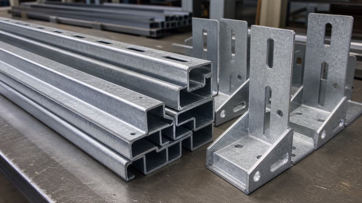
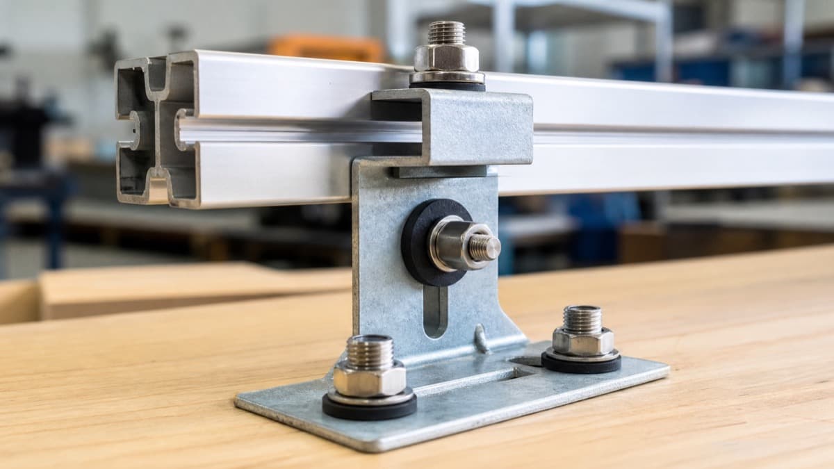
Rails & Purlins
Primary structural members supporting module rows. Typically hot-rolled or roll-formed C-channel, 10–14 gauge galvanized steel or extruded aluminum 6005-T5/6105-T5.
Mid & End Clamps
Module retention hardware. Extruded or die-cast aluminum 6061-T6 with serrated teeth for frame grip. Must maintain clamp force under thermal cycling (–40°F to +185°F / –40°C to +85°C).
Splice Plates & Connectors
Join rail sections end-to-end. Laser-cut and formed from 0.125–0.188″ (3.2–4.8 mm) galvanized steel or aluminum plate. Bolt-hole patterns must hold ±0.005″ positional tolerance.
Pier Caps & Base Plates
Interface between driven piles and rails. Typically 0.188–0.250″ (4.8–6.35 mm) galvanized A36 steel plate, laser-cut with CNC-formed flanges.
Cable Trays & Management
Wire management channels for DC home runs. Perforated or ladder-type, typically galvanized steel or aluminum. Must be UL-listed for outdoor use.
Grounding Lugs & Bonding Hardware
Electrical bonding points per NEC 690.43. Typically tin-plated copper or stainless 304/316L. Must maintain <1 Ω bonding resistance over system life.
Pro Tip
Design all BOS hardware for long-term service life to match standard PPA durations. Material degradation over this timeframe — not initial strength — is usually the governing design constraint.
Material Comparison: Head-to-Head
Four material classes dominate solar mounting hardware. This table compares their key mechanical, corrosion, and cost properties for utility-scale BOS applications.
| Property | Galv. Carbon Steel (A36) | Al 5052-H32 | Al 6061-T6 | SS 304 / 316L |
|---|---|---|---|---|
| Yield Strength | 36 ksi (248 MPa) | 28 ksi (193 MPa) | 42 ksi (290 MPa) | 30 ksi (205 MPa) / 25 ksi (170 MPa) |
| Tensile Strength | 58–80 ksi (400–550 MPa) | 33 ksi (228 MPa) | 45 ksi (310 MPa) | 75 ksi (515 MPa) / 70 ksi (485 MPa) |
| Density | 7.85 g/cm³ (0.284 lb/in³) | 2.68 g/cm³ (0.097 lb/in³) | 2.70 g/cm³ (0.098 lb/in³) | 7.99 g/cm³ (0.289 lb/in³) |
| Corrosion Rating | Good (zinc sacrificial, est. 25–50 yr inland) | Very Good (natural oxide layer) | Good (anodize or powder coat recommended) | Excellent (304) / Outstanding (316L coastal) |
| Formability | Good (1× thickness min bend radius) | Excellent (0.5× thickness bend radius) | Moderate (1–1.5× thickness bend radius) | Good (requires higher tonnage) |
| Weldability | Excellent (MIG/stick) | Good (TIG, filler 5356) | Good (loses T6 in HAZ) | Excellent (TIG/MIG) |
| UV Resistance | N/A (zinc coating degrades, not base metal) | Excellent (no organic degradation) | Good (anodize + powder coat for UV) | Excellent |
| Approx. Cost (raw stock, 2026) | ~$0.80–1.20/lb (galv.) (~$1.8–2.6/kg) | ~$2.50–4.00/lb (~$5.5–8.8/kg) | ~$3.00–5.00/lb (~$6.6–11/kg) | ~$4.00–7.00/lb (304) (~$8.8–15/kg) / ~$5.00–9.00/lb (316L) (~$11–20/kg) |
| Best Application | Ground-mount rails, pier caps, base plates | Rooftop rails, tracker torque tubes, clamps | Structural clamps, splice plates, extrusions | Grounding lugs, coastal hardware, fasteners |
Selection Shortcut
For 80%+ of continental U.S. ground-mount projects, galvanized A36 steel for structural members + aluminum 6061-T6 for clamps + stainless 304 fasteners is the cost-optimal combination. Reserve 316L and anodized aluminum for coastal or high-corrosion sites.
Need Solar Mounting Hardware Fabricated?
We laser-cut and CNC-form solar BOS hardware at production volumes — ready for your galvanizer. Upload your drawings for a quote.
Get Solar Hardware QuoteGalvanized Carbon Steel: The Workhorse
Hot-dip galvanized A36 carbon steel remains the dominant material for utility-scale ground-mount structures. The zinc coating per ASTM A153 provides sacrificial cathodic protection — the zinc corrodes preferentially, protecting the base steel even at cut edges and scratches.
ASTM A153 Class B1 Coating Specification
ASTM A153/A153M specifies hot-dip zinc coatings on iron and steel hardware. Class B1 (castings and large parts) requires a minimum coating weight of 1.5 oz/ft² (458 g/m²), which corresponds to approximately 2.1 mils (53 µm) per side. At typical inland corrosion rates of 0.1–0.2 mils/year (2.5–5 µm/year), this provides an expected coating life of an estimated 25–50 years before red rust appears (actual life depends on local corrosion rate, humidity, and atmospheric contaminants).
Design for Galvanizing (DFG) — Sheet Metal Constraints
Vent Holes for Closed Sections
Include vent holes (minimum 3/8″ / 10 mm diameter) in any closed or semi-closed section. These allow molten zinc to flow through during dipping and prevent dangerous steam pressure buildup from trapped moisture. Position vents at the highest point of each cavity when the part is in the dipping orientation.
Drainage Design
Add drain holes at low points to prevent zinc pooling. Pooled zinc creates uneven coating (lumps, drips, and runs) that interfere with mating surfaces. Minimum drain diameter: 3/8″ (10 mm). On U-channels, clip corners at 45° to aid flow.
Minimum Corner Radii
Maintain inside corner radii ≥ 1/8″ (3.2 mm) on all bends. Sharp corners cause zinc bridging (thin spots) and are stress risers that can crack during the thermal shock of immersion in 840°F (449°C) molten zinc. Radius = 1× material thickness is ideal.
Avoid Overlapping Joints
Overlapping seams and spot-welded joints trap flux and moisture, creating bare spots (uncoated areas) and outgassing during galvanizing. Use continuous welds or leave gaps ≥ 1/16″ (1.6 mm) for zinc penetration.
Dimensional Tolerance Impact
Hot-dip galvanizing adds 0.003–0.005″ (0.08–0.13 mm) per side from zinc buildup. Account for this on mating surfaces: oversize holes by 0.010″ (0.25 mm) diameter for bolt clearance. Slot lengths may need +0.010″ to maintain adjustment range.
Material Compatibility
Use silicon-killed or aluminum-killed A36 steel for predictable galvanizing results. Reactive (high-silicon) steels (Si > 0.25%) produce thick, matte-gray coatings that are structurally sound but aesthetically different. Specify Si < 0.04% or Si 0.15–0.25% to avoid the Sandelin effect.
Pro Tip
For high-volume solar racking (10,000+ pieces), negotiate galvanizing as a line item with your galvanizer directly rather than through the sheet metal shop. Batch scheduling and dedicated kettle time can reduce galvanizing cost by 15–25%.
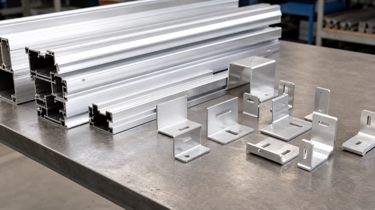
Aluminum Alloys: 5052-H32 vs 6061-T6
Aluminum delivers a 65% weight reduction over steel (2.68–2.70 vs 7.85 g/cm³) with inherent corrosion resistance from its natural oxide layer. Two alloys dominate solar mounting: 5052-H32 for formability and 6061-T6 for structural strength.
| Property | 5052-H32 | 6061-T6 |
|---|---|---|
| Yield Strength | 28 ksi (193 MPa) | 42 ksi (290 MPa) |
| Tensile Strength | 33 ksi (228 MPa) | 45 ksi (310 MPa) |
| Elongation | 12–18% | 8–12% |
| Min Bend Radius (90°) | 0.5× thickness (excellent) | 1–1.5× thickness |
| Weldability | Excellent (filler 5356) | Good (loses T6 temper in HAZ — drops to ~50% yield) |
| Extrusion Compatibility | Not extrudable (wrought only) | Excellent — most solar extrusions are 6061 or 6005/6105 |
| Corrosion Resistance | Very good (best of common Al alloys for marine) | Good (anodize or powder coat for severe environments) |
| Surface Treatment | Mill finish or chromate conversion | Type II/III anodize + powder coat for UV/salt |
| Best Solar Application | Formed brackets, cable tray, thin-gauge clamps | Structural rail extrusions, module clamps, splice plates |
| Cost (sheet/plate) | $2.50–4.00/lb ($5.5–8.8/kg) | $3.00–5.00/lb ($6.6–11/kg) |
Surface Protection: Anodize + Powder Coat
For outdoor solar installations exposed to UV and salt spray, bare aluminum is insufficient for long-term outdoor life. The standard protection stack is: Type III hard anodize (MIL-A-8625 Type III, Class 1, 0.002″ / 50 µm minimum) followed by TGIC polyester powder coat (2.5–3.0 mils / 63–76 µm). This combination provides UV stability, salt spray resistance (>3,000 hours ASTM B117), and abrasion resistance for field handling. For non-structural components, Type II clear anodize (0.0007″ / 18 µm) with a quality seal is acceptable in non-coastal environments.
Pro Tip
For formed sheet metal brackets, default to 5052-H32 — its 0.5× thickness bend radius eliminates cracking on tight bends common in cable tray and Z-clips. Use 6061-T6 only when you need >28 ksi (>193 MPa) yield or an extruded profile.
Stainless Steel: 304 vs 316L
Stainless steel in solar BOS is primarily used for fasteners, grounding hardware, and components in high-corrosion environments. The choice between 304 and 316L comes down to one factor: chloride exposure.
304 stainless steel (18% Cr, 8% Ni) provides very good general corrosion resistance and is the default grade for solar fasteners (hex bolts, flange nuts, washers) in inland environments. Yield strength: 30 ksi (205 MPa). Adequate for all but the most aggressive sites.
316L stainless steel (16% Cr, 10% Ni, 2–3% Mo) adds molybdenum for significantly improved chloride pitting resistance. Yield strength: 25 ksi (170 MPa) — slightly lower than 304, but the corrosion benefit is decisive for coastal installations within 1 mile (1.6 km) of saltwater. The "L" (low carbon, ≤0.03% C) version resists sensitization during welding.
| Criteria | Use 304 | Use 316L |
|---|---|---|
| Site Location | >1 mile (1.6 km) from coast | ≤1 mile from coast or saltwater bodies |
| Chloride Exposure | Low (inland, dry desert) | High (salt spray, coastal humidity) |
| Fastener Application | Standard structural bolts & nuts | Grounding lugs, bonding jumpers |
| Cost Premium | Baseline stainless | +20–30% over 304 |
| Passivation | Recommended (ASTM A967 citric acid) | Required (ASTM A967, nitric acid or citric acid) |
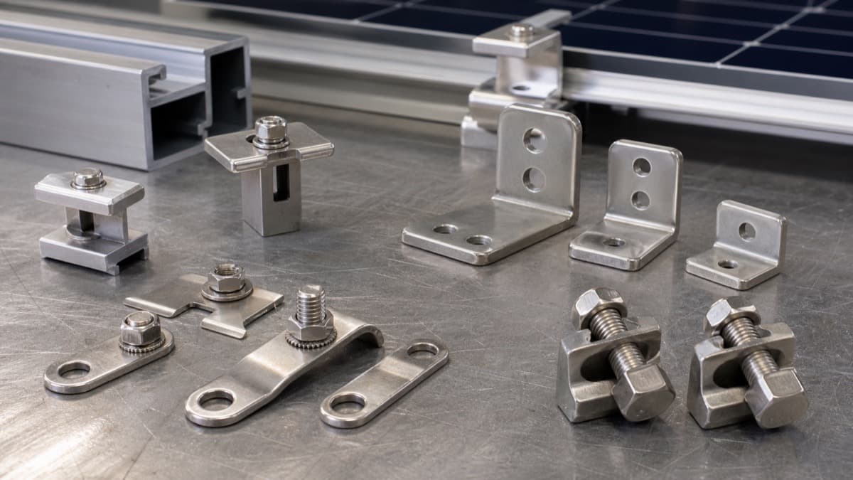
Critical: Passivation
All stainless steel solar hardware should be passivated per ASTM A967/A967M after fabrication. Passivation removes free iron contamination from machining/forming and restores the chromium oxide layer that provides corrosion resistance. Without passivation, stainless fasteners can develop tea staining (surface rust) within months of outdoor exposure — a cosmetic issue that erodes installer and end-customer confidence.
UL 2703 Compliance Considerations
UL 2703 is the safety standard governing mounting systems, racking, and clamping for photovoltaic modules. Material selection directly impacts three critical compliance areas.
Electrical Bonding & Grounding
All metallic mounting components must maintain equipment grounding continuity per NEC 690.43. Bonding resistance must be <1 Ω at each joint over the system life. Material choice affects this: aluminum-to-aluminum joints require serrated washers or WEEB clips to cut through the oxide layer; galvanized steel-to-aluminum joints need isolation to prevent galvanic corrosion that increases resistance over time. Stainless 304/316L grounding lugs are preferred for critical bonding points.
Fire Classification
UL 2703 classifies mounting systems as Type 1 (passed spread-of-flame test on Class A roof), Type 2 (Class B), or Type 3 (Class C). The mounting material itself is non-combustible (steel, aluminum, stainless are all non-combustible), but the system design — including plastic components (wire clips, end caps, module spacers) and gap distances — determines the fire class. All-metal hardware with no combustible components simplifies Type 1 certification.
Corrosion & Dissimilar Metals
UL 2703 requires evaluation of galvanic corrosion at dissimilar metal contacts. The galvanic potential between aluminum (–0.76 V) and carbon steel (–0.44 V) is 0.32 V — enough to cause accelerated corrosion in wet environments. Mitigation: use stainless fasteners (closer to aluminum on the galvanic series), apply isolating barriers, or specify galvanized steel (zinc at –0.76 V is nearly identical to aluminum, minimizing galvanic potential).
Corrosion Considerations by Site Class
Site environment is the single largest variable in material degradation rate. A galvanized steel bracket lasting 50 years in Phoenix may last only 10–15 years in Galveston. Match your material selection to the actual site conditions.
Desert / Arid
Key Corrosion Factors
- Extreme UV exposure (1,800–2,200 kWh/m²/yr)
- Sand/dust abrasion on coatings
- Thermal cycling: 30–60°F (17–33°C) daily delta
- Low humidity — slow corrosion rates
Recommendation
Galvanized A36 steel is ideal — estimated zinc coating life of 40–50+ years in arid conditions (varies by local factors). Use UV-resistant powder coat on aluminum (TGIC polyester, not epoxy — epoxy chalks under UV). Sand abrasion on tracker moving parts may require hard anodize (Type III) on aluminum bearing surfaces.
Coastal / Marine
Key Corrosion Factors
- Airborne chloride (salt spray) — primary corrosion driver
- High humidity accelerates electrochemical corrosion
- Galvanic corrosion at dissimilar metal joints
- Galvanized zinc life drops to 10–20 years near coast
Recommendation
Within 1 mile (1.6 km) of saltwater: aluminum 5052/6061 with anodize + powder coat for structural members, 316L stainless for fasteners and grounding. Galvanized steel is acceptable >1 mile from coast but specify ASTM A153 Class B1 minimum. Consider duplex coating (galvanize + paint) for steel in moderate marine zones.
Tropical / Humid
Key Corrosion Factors
- Sustained high humidity (>80% RH) year-round
- Combined UV + moisture degrades organic coatings
- Biological growth (mold, algae) on surfaces
- Acidic rain in some tropical regions
Recommendation
Use aluminum with Type III hard anodize for primary structure — aluminum is not affected by biological growth. For fasteners, 316L stainless with passivation per ASTM A967. Galvanized steel is acceptable if specified to ASTM A153 Class B1, but expect zinc life of 20–30 years. Avoid bare carbon steel entirely.
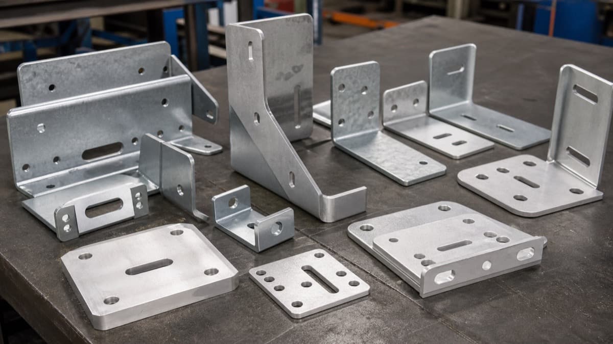
Sheet Metal Fabrication Specifications
Solar mounting hardware is predominantly sheet metal fabricated — laser-cut profiles with CNC press brake forming. Here are the standard tolerances and specifications for production-volume solar racking components.
| Parameter | Standard Tolerance | Precision | Notes |
|---|---|---|---|
| Laser Cut Profile | ±0.005″ (±0.13 mm) | ±0.003″ (±0.08 mm) | CO₂ or fiber laser. Fiber laser preferred for <0.125″ for edge quality. |
| Hole Position (Laser) | ±0.005″ (±0.13 mm) | ±0.003″ (±0.08 mm) | True position from datum. Critical for bolt patterns. |
| Bend Location (CNC Brake) | ±0.010″ (±0.25 mm) | ±0.005″ (±0.13 mm) | Measured from bend line to nearest feature. |
| Bend Angle | ±1° | ±0.5° | Springback compensation varies by material and grain direction. |
| Flatness (After Forming) | 0.010″/ft (0.8 mm/m) | 0.005″/ft (0.4 mm/m) | Leveling available for critical base plates. |
| Typical Thickness Range | 0.060–0.250″ (1.5–6.35 mm) | — | Most solar BOS hardware falls in 10–16 gauge range. |
| Hardware Insertion (PEM) | ±0.003″ (±0.08 mm) | ±0.002″ (±0.05 mm) | Clinch nuts, studs, standoffs. Specify per IFI-100 Series. |
Pro Tip
Design bolt holes as slots (e.g., 7/16″ × 13/16″ for 3/8″ bolts) rather than round holes wherever possible. Slots absorb fabrication tolerance stack-up and thermal expansion, reducing field installation time and allowing ±0.010″ adjustment — which is the difference between a 1-minute and a 5-minute field connection.
Cost Optimization & DFM Tips
Solar BOS hardware is a volume game — even a $0.05/part savings scales to $50,000 on a million-piece run. These DFM strategies target the largest cost drivers in solar mounting fabrication.
Galvanize vs Anodize: Decision Framework
Galvanizing is typically 40–60% cheaper than anodize + powder coat per square foot of surface area (actual savings vary by part geometry and volume). Default to galvanized steel for ground-mount projects >1 mile from coast. Reserve anodized aluminum for rooftop (weight-limited) or coastal installations where zinc life is insufficient.
Batch Sizing for Coatings
Hot-dip galvanizing has a significant fixed cost per batch (kettle setup, flux bath). Minimum efficient batch: 2,000–5,000 lbs. Anodizing lines typically have a minimum rack charge of $200–$400. Coordinate deliveries to consolidate coating batches — running 10 part numbers in one galvanizing batch vs 10 separate batches can save 30–40% on coating cost.
Material Gauge Standardization
Standardize on 2–3 sheet gauges across your product line (e.g., 12 ga / 0.105″ for structural, 14 ga / 0.075″ for non-structural, 16 ga / 0.060″ for light brackets). Fewer gauges = fewer material changeovers on the laser and brake, which reduces setup time and scrap.
Nesting Efficiency
Design part profiles to nest efficiently on standard sheet sizes (48″ × 120″ or 60″ × 120″). Rectangular parts with minimal cutouts achieve 85–92% material utilization. Complex profiles with large interior cutouts drop to 60–70%. DFM review should include a nesting study at the quoting stage.
Eliminate Secondary Operations
Every secondary operation (deburring, countersinking, tapping, hardware insertion) adds handling cost. Design features into the laser cut where possible: laser-cut countersinks, formed louvers instead of machined vents, and self-clinching hardware (PEM inserts) instead of weld nuts.
Slot-Based Assembly Design
Use tab-and-slot interlocking features to self-locate parts during assembly. This reduces the number of fasteners, eliminates jigs, and cuts welding time. A well-designed tab-slot bracket can reduce total assembly cost by 20–35% vs a conventional bolt-together design.
Frequently Asked Questions
Related Resources
Ready to Fabricate Solar Mounting Hardware?
Upload your CAD files for an engineer-reviewed quote on utility-scale solar BOS hardware, from prototype brackets to production runs.
Get Solar Hardware Quote