Acetal Plastic Gears: Design Rules and Material Guide
Acetal is the default material for precision plastic gears. Module selection, PV limits, tooth profile rules, and POM-on-steel pairing — all in one engineering reference.
Size the Gear First. Choose the Material Second.
The most common mistake in plastic gear design is selecting the module by intuition and then checking if acetal can handle it. The correct sequence: calculate required torque → determine pitch diameter and face width from Lewis bending equation → check pitch line velocity against PV limit → confirm acetal as the material. Only then should you consider PTFE-filled grades, nylon, or metal as alternatives if the initial sizing fails.
Why Acetal Is the Default Plastic Gear Material
If you're designing a plastic gear and haven't chosen a material yet, acetal POM should be your default — here's why. Acetal outperforms all commodity engineering plastics in the specific combination of properties required for gear service.
Stiffness
Tensile modulus 3,100 MPa — 4.5× stiffer than UHMW and 1.9× stiffer than nylon PA6 at service humidity (conditioned, 50% RH). Stiff tooth geometry transmits load efficiently and resists tip deflection under load. Deflection changes effective pressure angle and increases sliding velocity — both reduce gear life.
Natural Lubricity
Dry CoF against steel 0.20–0.35 without added lubricant. POM develops a thin transfer film on the mating surface that further reduces friction over time. This allows dry-running gear trains in sealed enclosures where periodic lubrication is impractical.
Dimensional Stability
Less than 0.9% moisture absorption ensures tooth pitch and mesh center distance hold their designed values in variable-humidity environments. Nylon gears in humid environments can swell sufficiently to eliminate backlash — causing binding and overload.

Module Selection for Acetal Gears
Module (metric) or Diametral Pitch (imperial) selection drives tooth size, bending strength, and contact stress. Use this table as a starting point — always verify with the Lewis bending equation for your specific torque and speed.
Worked Example: Sizing a Module 2 Acetal Gear
Given: Module (m) = 2 mm, Number of teeth (N) = 20, Face width (b) = 12 mm, Pressure angle = 20°
Step 1 — Pitch diameter: d = m × N = 2 × 20 = 40 mm (1.575 in.)
Step 2 — Lewis form factor: Y ≈ 0.32 for 20 teeth at 20° pressure angle (from AGMA 218.01 tables)
Step 3 — Allowable tooth load:
Wt = 25 MPa × 12 mm × 2 mm × 0.32 = 192 N
Step 4 — Torque at pitch circle:
Step 5 — Apply safety factor and velocity derating: At 500 RPM, pitch line velocity = π × 0.040 × 500 / 60 = 1.05 m/s. Barth velocity factor Kv = 3.05 / (3.05 + 1.05) = 0.74. With 2× safety factor:
Result: A Module 2, 20-tooth, 12 mm face width acetal gear can safely transmit approximately 1.4 N·m at 500 RPM — enough for a small conveyor indexer or a light-duty rotary actuator. At lower speeds (100 RPM), the same gear handles ~1.9 N·m. Scale face width proportionally for higher torque requirements.
| Module (m) | Diametral Pitch | Tooth Height (approx.) | Typical Application | Acetal Manufacturing |
|---|---|---|---|---|
| M0.5 | DP 50 | 1.1 mm | Instruments, watches, micro drives | Hobbing or injection molding preferred over CNC — tooth too fine for reliable end milling |
| M0.8 | DP 32 | 1.8 mm | Small electronics, precision instruments | Gear hobbing; end milling marginal — requires 1.5 mm or smaller end mill |
| M1.0 | DP 25 | 2.25 mm | Light-duty drives, consumer electronics | CNC gear milling feasible; hobbing preferred for production |
| M1.5 | DP 17 | 3.4 mm | Small actuators, general-purpose light drives | CNC gear milling standard practice; good tolerance control |
| M2.0 | DP 12 | 4.5 mm | General purpose — most common small plastic gear | CNC gear milling excellent; standard for prototype and low-volume production |
| M3.0 | DP 8 | 6.75 mm | Medium-duty drives, small power transmission | CNC machining excellent; hobbing or form milling for production |
| M4.0 | DP 6 | 9.0 mm | Higher-load drives; larger pitch diameters | CNC machining straightforward; confirm Lewis stress at design loads |
| M5.0+ | DP 5 and below | 11.25 mm+ | Heavy-duty — consider metal at this module | CNC or hobbing; re-evaluate if metal gear is more appropriate at M5+ |
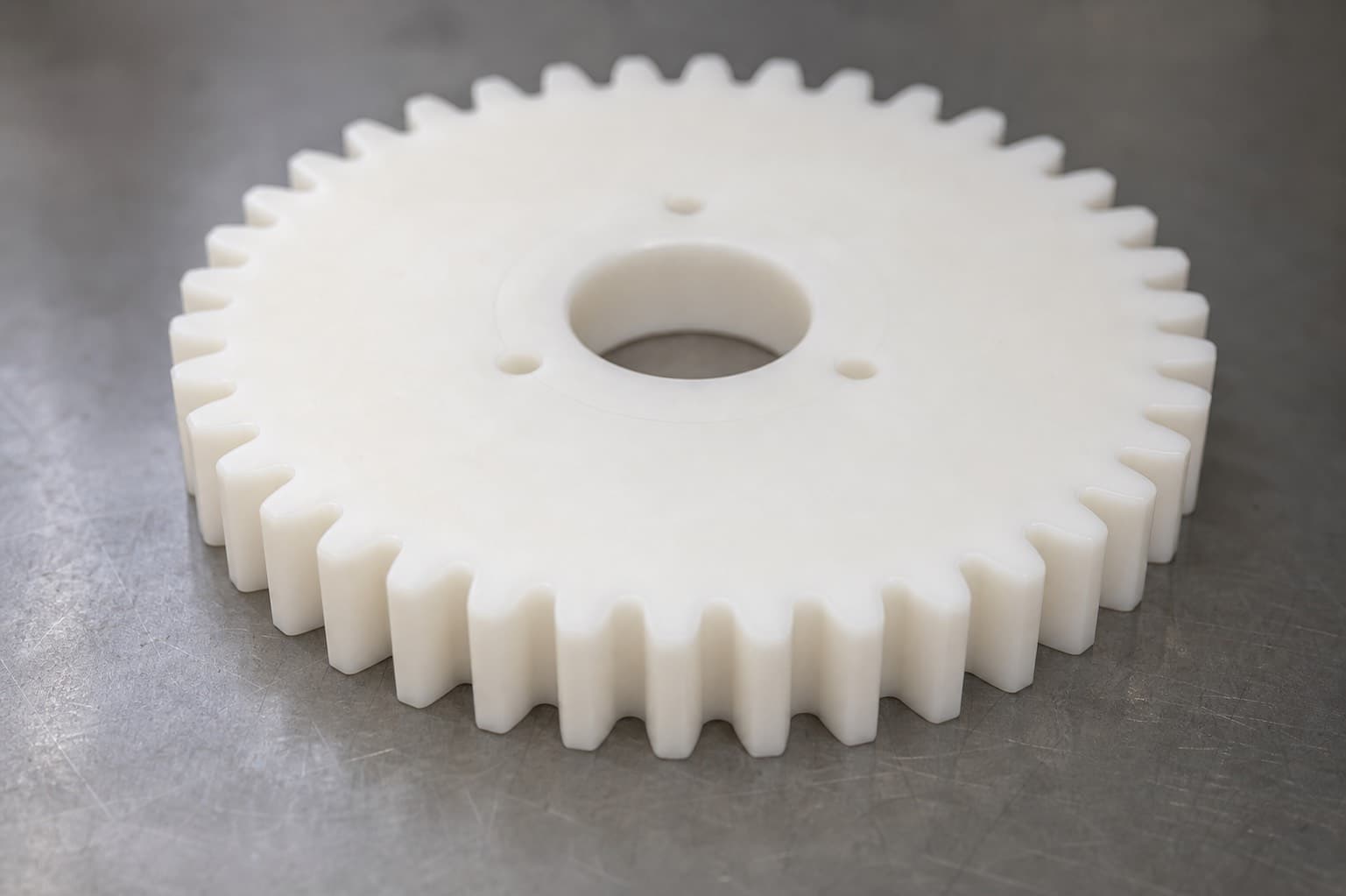
Tooth Profile Design Rules for Acetal
If you apply metal gear profile rules to your acetal gear, the teeth will fail prematurely at the root fillet. Plastic gear tooth geometry must accommodate the lower modulus and fatigue resistance of POM versus metal. These rules reduce tooth root stress and improve service life.
Pressure Angle: 20° full-depth involute
20° PA is the correct default for acetal gears. 14.5° stub tooth has lower tooth height and is not recommended for plastic — it produces higher Hertzian contact stress. 25° PA (high-pressure angle) can be used for higher load but reduces contact ratio and increases noise.
Tooth Root Fillet Radius: Minimum 0.3× module
A generous root fillet reduces stress concentration at the critical cross-section where bending failure initiates. For CNC machined gears, the root fillet radius is limited by the cutting tool tip radius. Specify minimum root radius explicitly — do not leave it to the machine shop default. For M2 gear: minimum root fillet 0.6 mm.
Face Width: 8–12× module
Face width in this range balances load capacity against manufacturing tolerance requirements. Very wide gears (> 15× module) require precise shaft parallelism that is difficult to achieve in plastic housings — concentrated edge loading increases actual stress beyond Lewis calculation predictions.
Minimum Number of Teeth: 12–14
Below 12 teeth, undercutting of the tooth root becomes severe in standard involute geometry, reducing effective tooth strength. For acetal, 14 minimum teeth is a conservative starting point that avoids significant undercut. Stub-tooth or long-addendum corrections can allow fewer teeth if needed.
Contact Ratio: ≥ 1.4
Contact ratio is the average number of tooth pairs in simultaneous contact. Higher contact ratio means load is shared across multiple teeth — reducing peak tooth stress. Full-depth involute gears with adequate tooth count typically achieve 1.5–1.7 contact ratio. Never design below 1.4 in plastic gears.
Tip Relief: Required at medium-to-high speed
Under load, acetal gear teeth deflect. Without tip relief, the incoming tooth tip contacts the root of the mating tooth prematurely, causing impact loading and accelerated wear. Specify tip relief of approximately 0.3–0.5× tooth deflection under rated load, starting 5–10° before the end of approach.
PV Limits and Pitch Line Velocity
If you skip the PV check on your acetal gear design, thermal softening will destroy the tooth surface before mechanical wear becomes an issue. PV limit (Pressure × Velocity) at the pitch cylinder determines whether the gear will thermally fail before mechanical failure. Exceeding the PV limit causes tooth surface to soften and deform — the leading cause of acetal gear failure.
| Acetal Grade | Max Pitch Line Velocity | Max PV (MPa·m/s) | Lubrication | Notes |
|---|---|---|---|---|
| Unfilled POM (Delrin 150) | 3 m/s (600 ft/min) | ~0.08 MPa·m/s | Dry | Conservative baseline — surface temperature stays below 140 F (60 C) |
| Unfilled POM with grease | 5 m/s (1,000 ft/min) | ~0.20 MPa·m/s | Grease lubricated | Grease significantly extends operating envelope |
| PTFE-filled (Delrin AF) | 4 m/s (800 ft/min) | ~0.15–0.20 MPa·m/s | Dry | Lower CoF extends dry PV limit by ~2× |
| Glass-filled acetal (25% GF) | 2 m/s (400 ft/min) | ~0.06 MPa·m/s | Dry | Higher friction CoF limits PV — but higher tooth strength for given module |
| Carbon-filled acetal (20% CF) | 3.5 m/s (700 ft/min) | ~0.12 MPa·m/s | Dry | CF self-lubricates — better dry PV than unfilled; stiffer tooth |
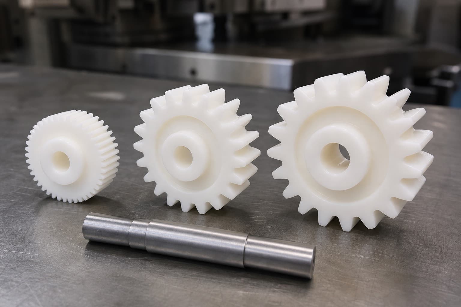
CNC Machined Acetal Gears with Quote Review
MakerStage CNC machines acetal gears in unfilled POM-H and POM-C from module 1.0 and larger. Upload your drawing or CAD file so the quote review can flag undercut, insufficient root radius, and face width concerns before production.
Get an Acetal Gear QuoteGear Material Pairing Guide
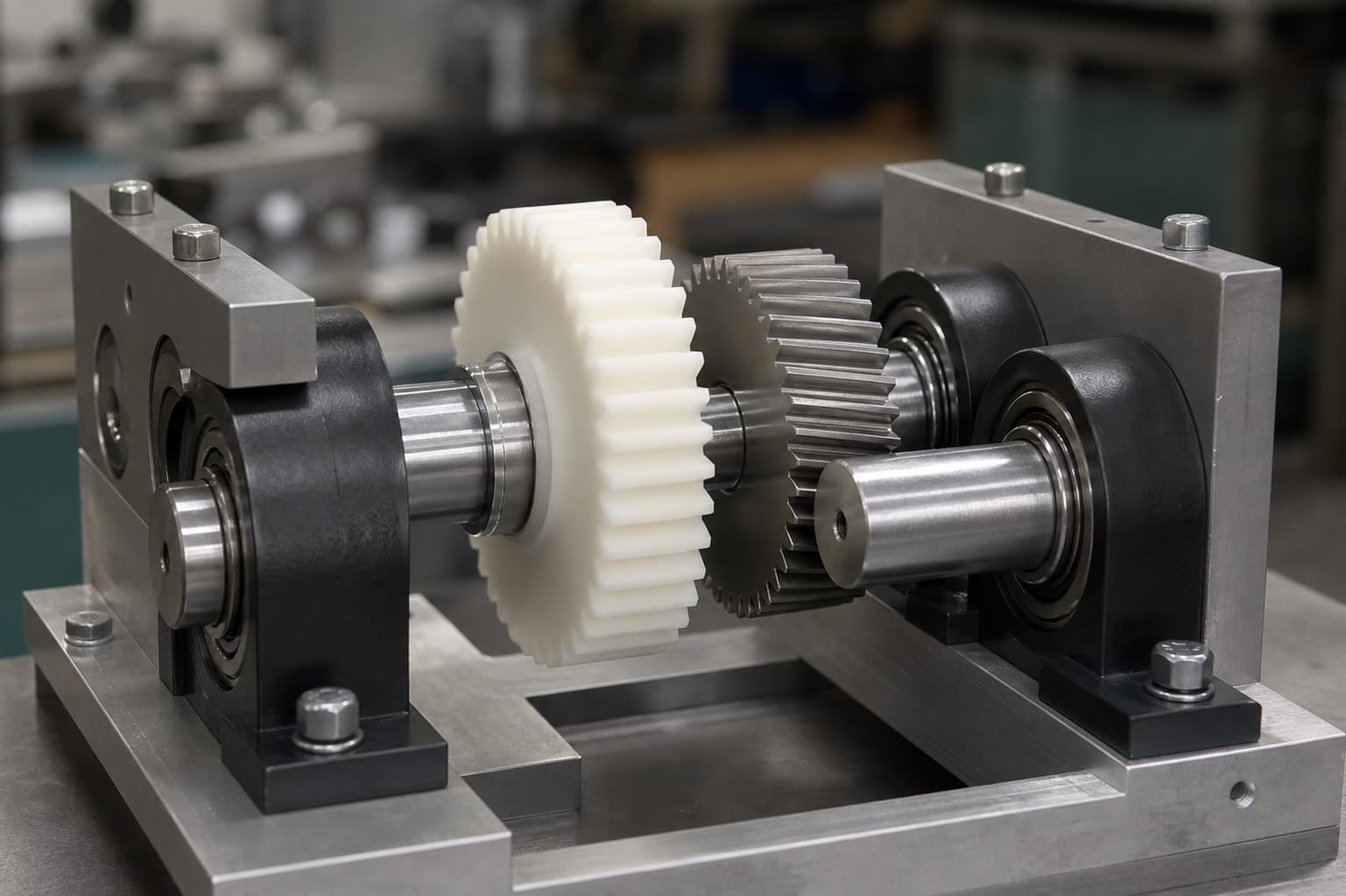
Your choice of mating gear material controls wear rate and noise as much as the acetal grade itself. The mating material choice affects wear rate, noise, and service life as much as the acetal grade itself.
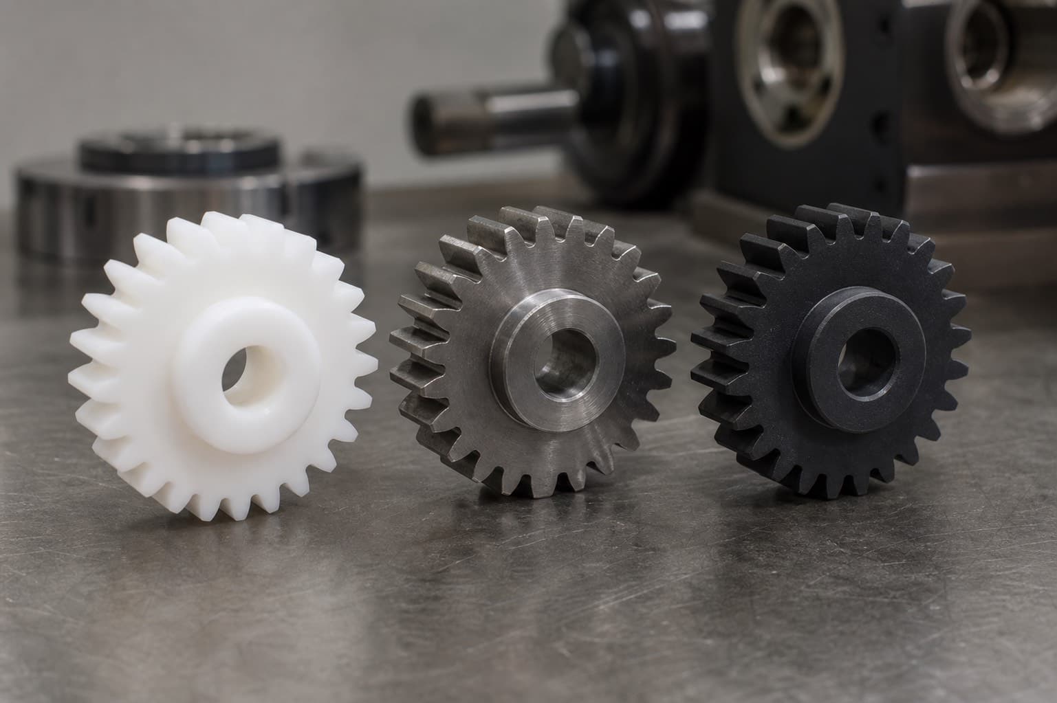
| Acetal Gear Paired With | Wear Performance | Noise | Notes |
|---|---|---|---|
| Hardened steel (HRC 45+, ground Ra 0.8–1.6 µm / 32–63 microinches) | Excellent | Moderate | Standard pairing for power transmission. Hard, smooth steel allows POM transfer film to form. Rough or soft steel accelerates POM wear. |
| Stainless steel 17-4 PH (H900) | Good to Excellent | Moderate | Good for food/medical applications. Hardness HRC 40+ adequate with smooth surface. |
| Acetal POM (plastic-on-plastic) | Good at low PV | Low | Both gears generate low heat; quiet meshing. Service life lower than POM-on-steel for equal load. |
| Nylon PA6/6 (mating gear) | Good | Very Low | Quiet — dissimilar plastic pairs run with low noise. Nylon absorbs moisture — center distance may change. |
| Aluminum (6061, 7075) | Poor — avoid | High | Acetal wears aluminum rapidly. Aluminum surface too soft for sustained POM contact. Use anodized or Ni-plated Al as minimum. |
| Brass | Fair | Low | Soft — brass wears under sustained contact. Use only for very light loads or intermittent service. |
| Cast iron | Good | Moderate to Low | Cast iron surface is self-lubricating (graphite inclusions) — compatible with acetal. Confirm surface hardness. |
Further Reading
- What Is Acetal (POM/Delrin)? Complete Engineer's Guide — hub guide with all acetal properties.
- Acetal Filled Grades: PTFE, Glass, Carbon Compared — when to upgrade to AF grade for higher-PV gears.
- CNC Machining Acetal (POM/Delrin): Speeds, Feeds, and Design Rules — machining reference.
Frequently Asked Questions
CNC Machined Acetal Gears — 5–7 Day Lead Time
Module 1.0 and larger, unfilled and PTFE-filled acetal. Engineer-reviewed pricing helps confirm tooth profile and module fit before production.
Get an Acetal Gear Quote