CNC Machining Acetal (POM/Delrin): Speeds, Feeds & Design Rules
Acetal is widely considered the most machinable engineering plastic. Here is exactly how to machine it — cutting parameters, tool selection, defect prevention, and DFM checklist.
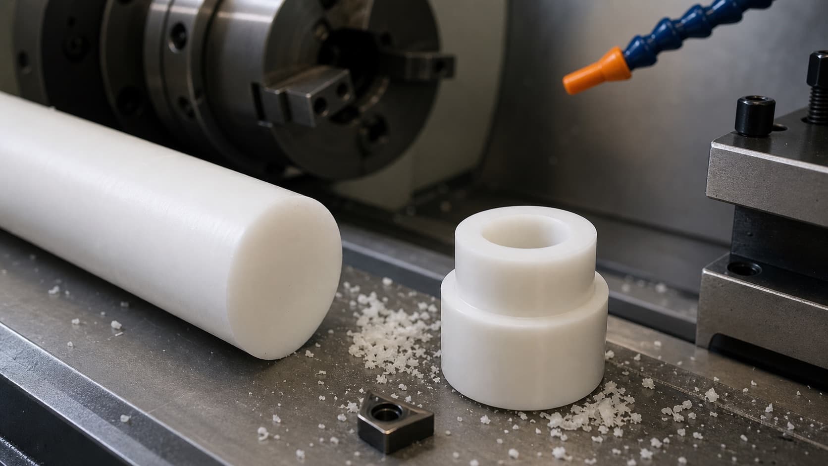
Acetal Behaves More Like Soft Aluminum Than Like Other Plastics.
Engineers who have struggled with nylon's stringy chips or polycarbonate's thermal sensitivity are often surprised by how cleanly acetal machines. POM produces short, predictable chips at high speeds, holds tight tolerances without humidity conditioning, and requires no coolant. The key variables to control are tool sharpness and depth of cut on thin walls. Get those right and acetal is a pleasure to machine.
Why Acetal Machines So Well
Understanding the material behavior helps you set up cuts correctly from the start, not after the first scrap part.
Semi-Crystalline Structure
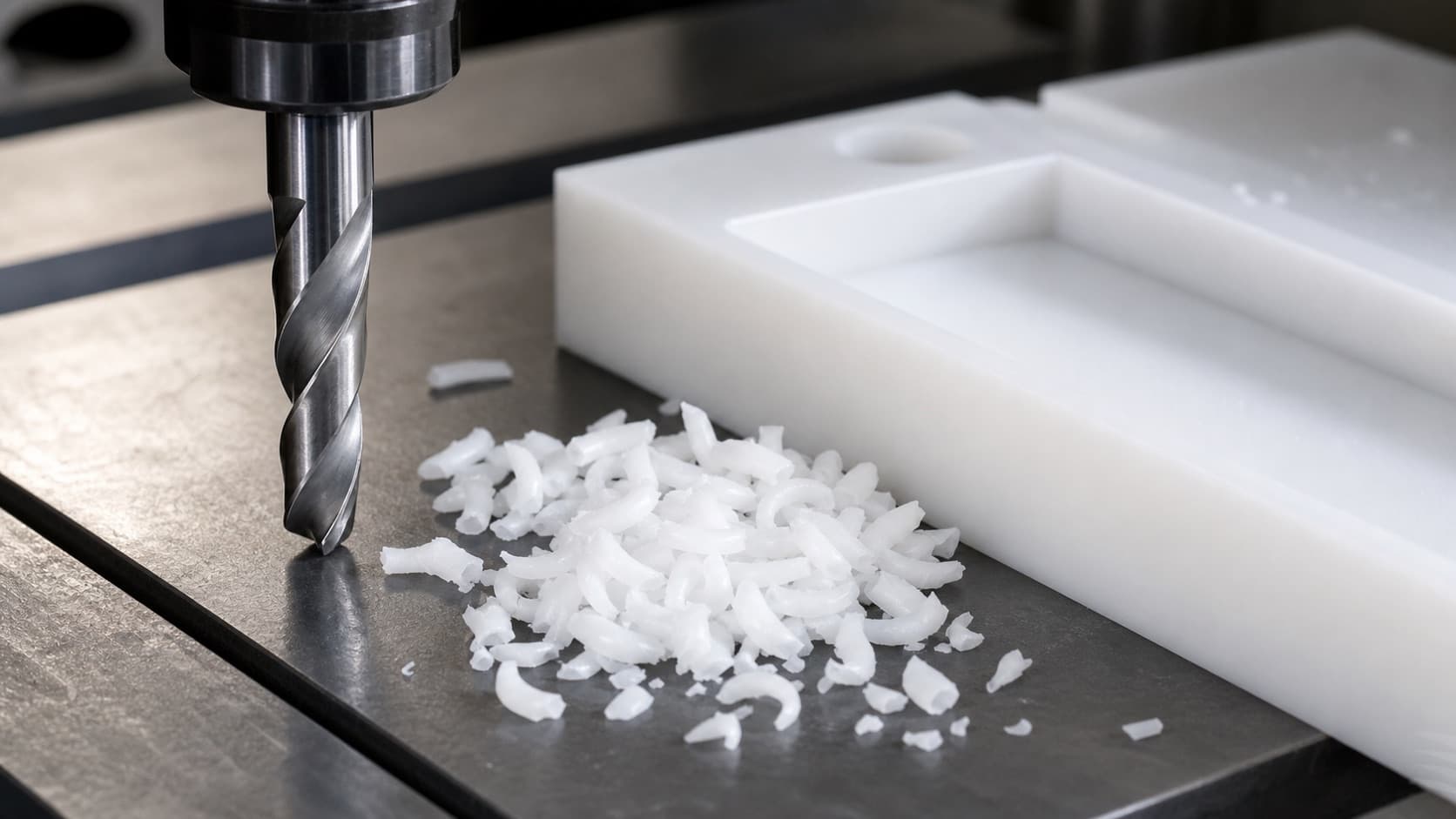
POM's high crystallinity (75–85%) makes it behave like a hard, brittle solid at the cutting edge — chips fracture cleanly rather than tearing. This is why acetal chips are short and predictable, unlike amorphous plastics (PC, ABS) that tend to smear.
Low Thermal Sensitivity
POM has higher thermal conductivity (0.31 W/m·K) than most plastics and a relatively high melting point (347 °F (175 °C) for POM-H). The cutting zone stays below the thermal degradation point at normal plastic machining speeds. Compare to PTFE or polyethylene that melt and smear at modest speeds.
Dimensional Stability
Moisture absorption below 0.25% in 24 hours means the part dimensions do not change significantly between machining and inspection. With nylon, you must condition stock to equilibrium moisture content before machining to avoid tight dimensions "relaxing" after cutting. Acetal needs no conditioning.
Speeds and Feeds Reference
If you're setting up your first acetal job, start with these parameters — they work for unfilled POM on any standard CNC lathe or mill with carbide tooling. All values for unfilled acetal POM with standard uncoated carbide tooling. Filled grades (PTFE, glass) use the same parameters; carbon-filled grades may require slightly lower speeds due to increased tool wear from carbon fiber reinforcement.
| Operation | Cutting Speed | Feed Rate | Depth of Cut | Notes |
|---|---|---|---|---|
| OD Turning (roughing) | 300–500 SFM (90–150 m/min) | 0.006–0.010 in/rev (0.15–0.25 mm/rev) | 0.050–0.150 in (1.3–3.8 mm) | Carbide insert, positive rake, sharp edge |
| OD Turning (finishing) | 400–600 SFM (120–180 m/min) | 0.002–0.005 in/rev (0.05–0.13 mm/rev) | 0.005–0.020 in (0.13–0.51 mm) | Sharp insert mandatory — dull insert smears POM |
| Boring (ID turning) | 300–500 SFM (90–150 m/min) | 0.003–0.007 in/rev (0.08–0.18 mm/rev) | 0.030–0.100 in (0.8–2.5 mm) | Compressed air for chip clearing in deep bores |
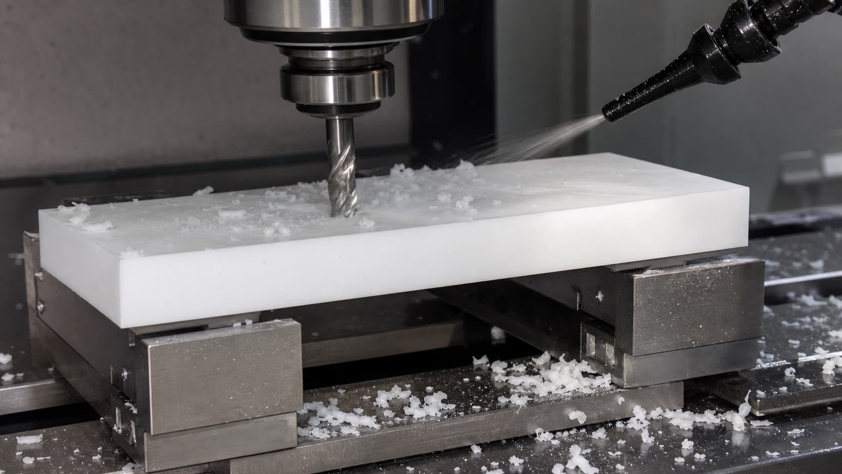
| Face milling | 5,000–8,000 RPM (1 in cutter) | 0.005–0.008 in/tooth (0.13–0.20 mm/tooth) | 0.020–0.060 in (0.5–1.5 mm) | Positive rake face mill; climb milling preferred |
| End milling (slot/pocket) | 6,000–10,000 RPM (1/2 in EM) | 80–150 in/min (2,000–3,800 mm/min) | Axial: 0.5–1.0× dia; Radial: 0.3–0.5× dia | 2-flute high-helix; reduce radial DOC for deep walls |
| End milling (finishing pass) | 8,000–12,000 RPM (1/2 in EM) | 100–200 in/min (2,500–5,100 mm/min) | Axial: 0.5× dia; Radial: 0.005–0.020 in | Light spring pass improves surface finish to Ra 32–63 µin (Ra 0.8–1.6 um) |
| Drilling | 3,000–5,000 RPM (1/4 in drill) | 0.004–0.008 in/rev (0.10–0.20 mm/rev) | Full diameter | Standard HSS or carbide; frequent peck cycles on deep holes |
| Tapping | 200–400 RPM | Governed by pitch | Through or blind | Standard taps; no oversized pilot holes needed (unlike nylon) |
| Reaming | 500–1,000 RPM | 0.005–0.012 in/rev (0.13–0.30 mm/rev) | 0.005–0.015 in (0.13–0.38 mm) stock removal | Achieves H7 bore tolerances; use carbide or HSS spiral-flute reamer |
Start Fast, Then Optimize
Acetal is forgiving of aggressive initial parameters. Start at the high end of the speed range and observe chip character: clean, short chips (2–8 mm) indicate optimal cutting; long, stringy chips mean the tool is rubbing; powdery, hot chips mean the material is melting rather than cutting. Adjust from there. Unlike steel, over-speed in acetal typically causes surface melt rather than catastrophic tool failure.
Tool Selection and Geometry
Your tool geometry matters more than your machine when cutting acetal — the wrong cutter will melt and smear POM regardless of your speeds and feeds. Tool geometry matters more than material in plastic machining. The key principle: sharp, positive-rake geometry that cuts cleanly rather than pushing the material.
Turning Inserts
- Grade: Uncoated carbide (K10–K20); TiN-coated acceptable but not required
- Geometry: Positive rake angle (10–15°); polished chipbreaker face
- Nose radius: 0.016–0.031 in (0.4–0.8 mm) for finish passes; larger for roughing
- Edge prep: Ground and honed, never chipped — POM telegraphs tool wear immediately
- Tool life: Very long vs steel applications — change when surface quality degrades
End Mills
- Flutes: 2-flute preferred for slots and pockets; 3-flute acceptable for small depths
- Helix: 35–45° high-helix for chip evacuation out of the cut
- Grade: Uncoated carbide (C2/K10); TiAlN or DLC coatings acceptable
- Diameter: 1/4 in to 1/2 in most common; smaller for fine features
- Avoid: 4+ flute end mills in deep pockets — chip re-cutting damages acetal surface
Drills
- Standard HSS twist drills work well for diameters under 1/4 in
- For precision bores, drill undersize then ream to final dimension
- Step drills useful for non-standard diameters in sheet material
- Peck drill cycles for holes deeper than 3× diameter to prevent chip packing
- Acetal tends to grab at drill breakthrough — maintain feed rate through exit
Taps and Thread Mills
- Standard HSS or carbide taps in all common thread sizes
- No oversized pilot holes — acetal does not swell like nylon
- Spiral-flute taps (gun taps) for through holes; spiral-point for blind holes
- Thread milling preferred for tight-tolerance threads in precision work
- Avoid excessive tap speed — heat causes galling at thread root
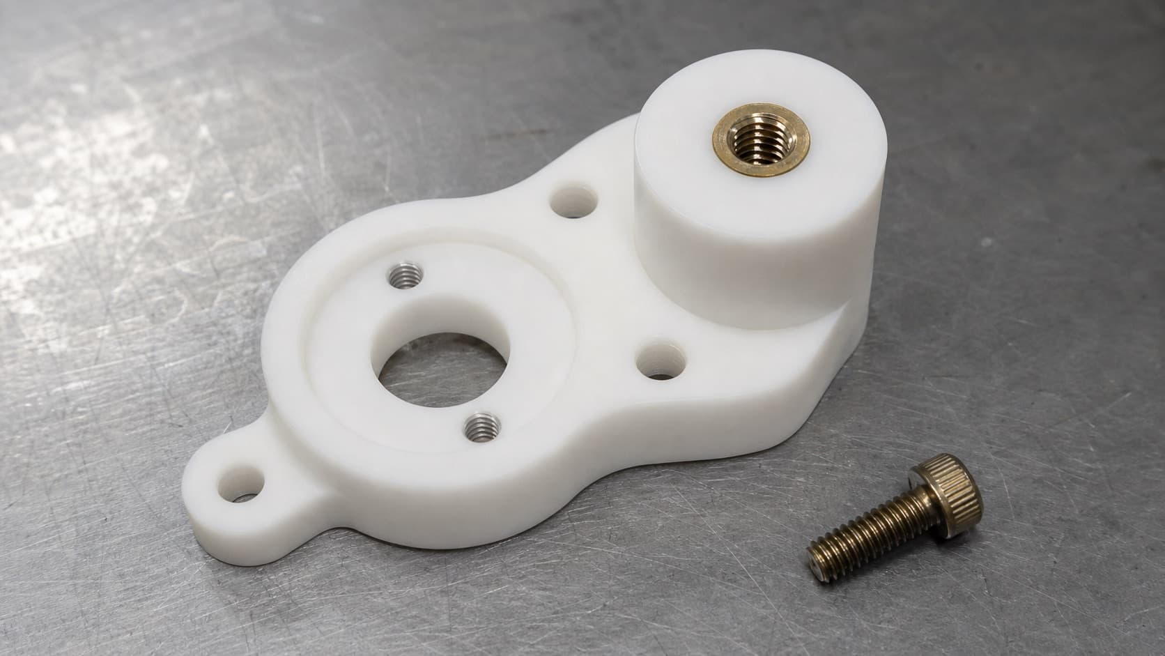
Tapped Holes vs. Thread Inserts
If your acetal part requires threaded fasteners, the thread size and number of assembly cycles determine whether you tap directly into POM or install brass inserts. Acetal threads are good — but they have limits. Knowing when to tap and when to insert is critical for parts that will be fastened and re-fastened in service.
| Thread Size | Recommended Approach | Torque Limit (approx.) | Notes |
|---|---|---|---|
| #4-40, #6-32, #8-32 | Tapped hole | 2–5 in·lb | Light duty — do not overtorque; stripped thread non-recoverable |
| 1/4-20 UNC | Tapped hole (light duty) or brass insert | 8–15 in·lb tapped; 30–50 in·lb with insert | If repeatedly assembled/disassembled, use brass press-fit insert |
| 5/16-18, 3/8-16 | Heat-set or ultrasonic brass insert | — | Tapped thread marginal at these sizes under structural load; insert preferred |
| M2, M3, M4 | Tapped hole (light duty) | 0.2–1.0 N·m | Acceptable for non-structural, non-repeated assembly |
| M5, M6 | Brass heat-set insert recommended | — | Tapped M6 in POM will strip at low torque — use insert for any structural fastening |
| M8, M10, M12 | Brass heat-set insert required | — | Always use inserts for M8 and above; tapped threads too weak for fastener torque spec |
Acetal Quote Review Before Production
MakerStage reviews acetal RFQs for machinability risks during quote review, including thread sizing, thin-wall flags, and tolerance callouts that may need special tooling before production starts.
Get a CNC Acetal QuoteCommon Defects and How to Prevent Them
Most acetal machining defects have one root cause: heat. Learn to read chip character as your primary process indicator.
Melted or smeared surface finish
Cause: Dull tool generating heat through rubbing rather than cutting; excessively high feed on finishing pass with dull insert
Fix: Replace tool — this defect cannot be fixed with parameter changes on a dull cutter. Sharp insert + reduced surface speed on finishing pass.
Chatter marks on OD surface
Cause: Part deflection in chuck (thin walls, long unsupported overhangs); excessive DOC on finishing pass
Fix: Use collet instead of 3-jaw chuck; reduce overhang; take lighter finishing passes; ensure steady rest support for long parts
Chips packing in deep bores or blind holes
Cause: POM chips do not evacuate under gravity alone; no coolant to flush
Fix: Use peck drill cycles with full retract; add compressed air blast directed into bore; increase peck depth cycle frequency
Oversized bore after reaming
Cause: Reamer deflection in thin-wall section; incorrect reamer allowance (acetal springs back less than metals)
Fix: Leave 0.005–0.010 in for reaming (less than metal practice); support thin walls with plug or fixture during reaming
Stripped tapped threads
Cause: Overtorquing fastener beyond POM bearing strength; thread too short (< 2× pitch diameter engagement)
Fix: Use brass heat-set insert for M5/1/4-20 and above; ensure minimum 2× major diameter thread engagement
Centerline voids in bored ID (POM-H stock)
Cause: Pre-existing centerline porosity from rod manufacturing; typically >25 mm diameter stock
Fix: Specify POM-C copolymer for thick-section parts; inspect POM-H stock with sacrificial face cut before full production
DFM Checklist for Acetal Parts
Check these items before sending your CAD file for quoting. Each prevents a costly surprise.
Material Specification
- Drawing specifies POM-H or POM-C explicitly — not just "acetal"
- Stock thickness < 25 mm if POM-H specified; POM-C for thicker stock
- Color specified — natural (white) for FDA applications; black for others
- FDA-compliant grade called out if food or medical contact
Wall Thickness
- Minimum wall thickness ≥ 0.060 in (1.5 mm) for machined features
- Walls < 0.060 in: fixturing plan reviewed with machine shop before order
- Thin ribs: height-to-thickness ratio ≤ 5:1 without dedicated support fixture
- Thin-wall bores: fixture plan for reaming to tolerance without distortion
Threads and Fasteners
- Tapped holes ≤ #10-32 / M5: acceptable for light duty only
- Threads ≥ 1/4-20 / M6 under structural load: brass insert called out on drawing
- Minimum thread engagement: 2× major diameter in acetal
- Fastener torque on drawing does not exceed POM bearing strength
Tolerances and Fits
- OD tolerances: ±0.002 in standard; ±0.001 in achievable, flag as precision
- Bore tolerances: ±0.001–0.002 in; H7 bore achievable with reaming
- No tolerances tighter than ±0.001 in without discussion of fixturing method
- Running fits: H7/f6 or H7/g6 standard for shafts through POM bushings
Feature Geometry
- Internal radii ≥ 10% of cavity depth for clean end mill passes
- Blind holes: specify flat bottom or radius at bottom, not assumed flat
- Undercuts and T-slots: noted explicitly; require live tooling or secondary setup
- Chamfers on all external sharp edges: prevents chipping in assembly and use
Surface Finish
- Default finish Ra 63–125 µin (Ra 1.6–3.2 um, machine finish) is appropriate for most applications
- Ra 32 µin (Ra 0.8 um) achievable with finishing pass — call out only where functionally needed
- Bearing surfaces and sliding fits: call out Ra 32–63 µin (Ra 0.8–1.6 um) explicitly
- No plating or painting on acetal — coatings do not adhere to POM
Further Reading
- Acetal CNC Tolerances: What's Achievable — quantified tolerance tables for turned OD, bored ID, flatness, and threads.
- What Is Acetal (POM/Delrin)? Complete Engineer's Guide — hub guide covering all acetal grades and properties.
- DFM Best Practices for CNC Machining — broader DFM rules covering metals and plastics.
Frequently Asked Questions
Ready to Machine Your Acetal Part?
CNC machining in Delrin (POM-H), acetal copolymer (POM-C), and filled grades. Share your CAD file so the quote review can flag tolerance and thread concerns before production.
Get an Acetal Quote