CNC Turning Services: Precision Rotational Parts From Bar Stock
CNC turning services are the right fit when your part is mostly diameters, bores, threads, grooves, and faces that all share one centerline. If the geometry is rotational, turning is usually faster, cleaner, and more repeatable than milling the same part from billet because the process starts with the physics described in this CNC machining overview: spin the material, move the tool, and keep every critical diameter concentric to the spindle axis.
What Is CNC Turning and How It Works
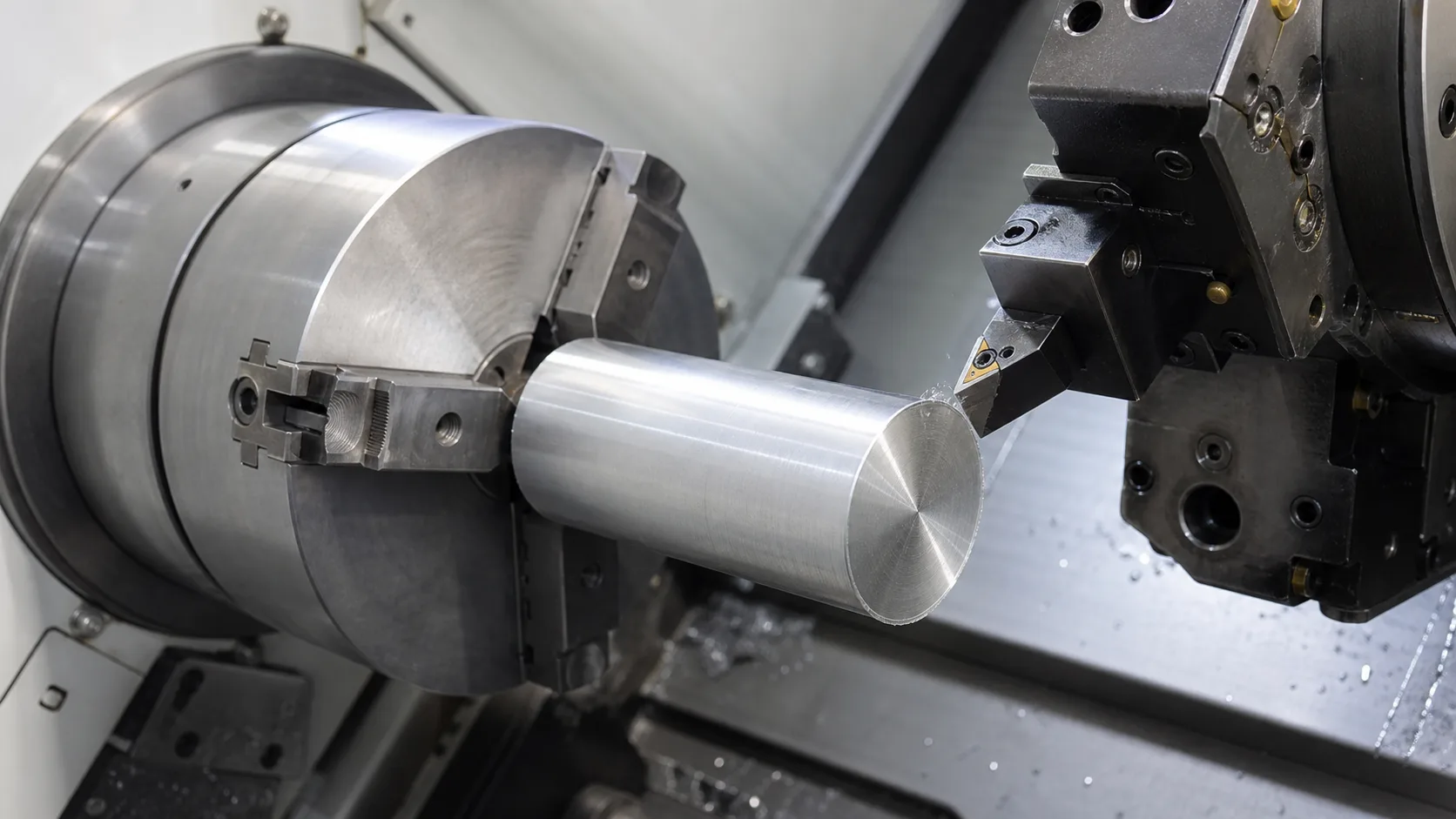
CNC turning is a subtractive process where a cylindrical workpiece rotates and a stationary or live cutting tool moves relative to that axis. The process exists because rotational geometry is easiest to make when the spindle defines the centerline, which is why turned parts naturally hold concentric outside diameters, inside diameters, shoulders, and threads more efficiently than a general-purpose milling setup.
Start with round bar stock
Turning is strongest when the raw material already matches the final part shape. Round stock minimizes wasted chip volume and makes concentric features natural.
Rotate the workpiece
The spindle spins the bar while the cutting tool feeds parallel or perpendicular to the centerline. That is why diameters, shoulders, and grooves are so efficient on a lathe.
Cut OD, ID, and faces
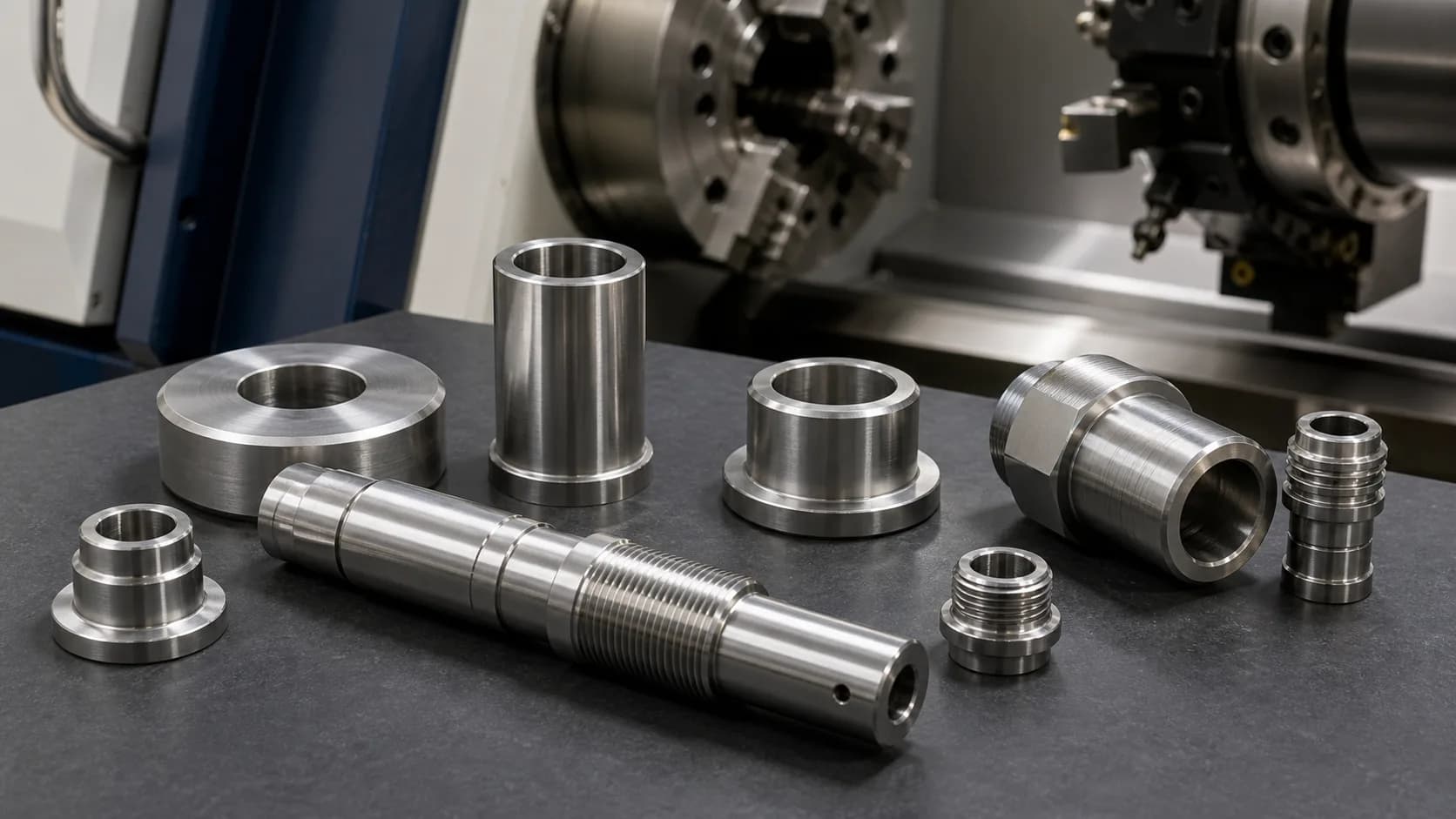
Turning tools rough and finish outside diameters, boring tools open inside diameters, and facing tools clean the end face. One setup can produce most rotational geometry.
Add secondary features if needed
Live tooling, sub-spindles, and C-axis positioning let the same machine add flats, cross-holes, and milled features before the part is cut off.
Why the process is so efficient for turned parts
When the feature is concentric to the spindle, the machine does not need to keep re-fixturing the part to create the next critical surface.
| Feature | Why turning handles it well | What to watch |
|---|---|---|
| OD diameters and stepped shafts | The rotating spindle naturally produces concentric diameters and shoulders without indexing the part. | Call out only the diameters that matter. Over-tolerancing every step drives cost without improving assembly function. |
| Bored IDs and concentric bores | The same setup can control OD-to-ID concentricity much better than moving the part between machines. | Deep bores need chip evacuation and tool rigidity planning. Blind bores often need extra clearance beyond the functional depth. |
| External and internal threads | Single-point threading, thread rolling, and live-tool thread milling all fit naturally in a turning workflow. | Specify thread depth, class, and relief clearly. Blind internal threads need additional drill depth below the usable thread length. |
| Grooves, undercuts, and cutoff faces | Grooving and part-off tools produce retaining-ring grooves, thread reliefs, and finished face geometry efficiently. | Keep groove widths aligned with standard insert widths when possible. Very narrow custom grooves add tool cost and process risk. |
CNC Turning vs CNC Milling: When to Use Each
The decision starts with geometry, not machine preference. If your part is mostly round, start with turning. If your part is mostly prismatic, start with milling. A hybrid workflow makes sense when one turned centerline controls fit, but the part also needs flats, slots, or cross-holes that are better handled with live tools or a second milling operation.
| Geometry or need | Turning | Milling |
|---|---|---|
| Mostly diameters, bores, grooves, and threads | Best starting process because features are concentric to the spindle axis. | Usually slower because the machine must remove extra stock from a billet. |
| Flats, pockets, rectangular faces, and bolt patterns | Possible only with live tooling, and usually only for limited off-axis content. | Best fit because the cutter approaches features from multiple orientations. |
| Long slender shafts | Strong choice with tailstock, steady rest, or Swiss support depending on L/D ratio. | Poor fit because workholding and cycle time become inefficient quickly. |
| Complex prismatic housings | Wrong first process unless there is one dominant bore or diameter that drives concentricity. | Best fit for multiple datums, pockets, bosses, and planar surfaces. |
A useful first-pass rule
If most function-critical features are diameters, bores, shoulders, or threads on one centerline, treat turning as the primary process. If the part's job depends on flats, large planar faces, or pocket geometry, turning becomes a supporting process, not the main one.
L/D ratio matters more than many RFQs admit
Once unsupported length-to-diameter ratio gets above about 3:1, rigidity planning becomes part of the design review. In practice, the handoff to a tailstock, steady rest, or the Swiss turning vs CNC turning decision often happens before you touch a tolerance callout.
Live Tooling and Multi-Axis Turning Capabilities
Live tooling exists because many real parts are not purely round. A fitting might need wrench flats. A shaft might need a cross-hole. A connector shell might need a milled slot. A CNC turning service with live tooling handles those features in the same machine so the turned datum stays consistent while the off-axis detail is added.
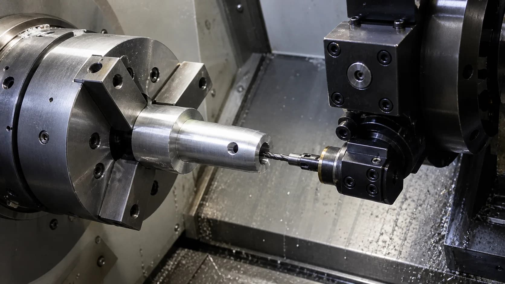
Cross-holes and radial drill features
Secondary op avoided: No handoff to a mill or drill fixture for basic off-axis drilling.
Why it matters: Feature location stays tied to the same spindle datum, which reduces runout and secondary setup variation.
Flats, wrench features, and milled slots
Secondary op avoided: No separate milling setup for simple indexed flats.
Why it matters: Good fit for fittings, connectors, shafts, and spacers that need limited non-round geometry.
Front and back working with a sub-spindle
Secondary op avoided: No manual flip operation for backside drilling or facing.
Why it matters: Improves length consistency and reduces handling when both ends of the part need finished features.
Choosing between a Swiss lathe and a dual-spindle with live tooling
The deciding factors are bar diameter, unsupported length-to-diameter ratio, and how much backside work the part needs.
Both machine types are turning centers, but they solve different problems.
Swiss-type lathes use a guide bushing that supports the workpiece close to the cutting tool. They are purpose-built for small-diameter, slender parts where unsupported deflection would otherwise dominate. Typical bar capacity is Ø0.08–1.50 in. (2–38 mm); most production Swiss machines are sized for bar ≤ Ø1.26 in. (32 mm). Live tooling is standard on modern Swiss machines, so cross-holes, flats, and milled slots run in the same cycle.
Dual-spindle CNC lathes with live tooling transfer the part between a main spindle and a sub-spindle, enabling front-and-back machining in one setup. Main-spindle bar capacity on mid-size machines is typically Ø1.5–2.6 in. (38–66 mm); chuck-held work reaches larger diameters on the workzone envelope. C- and Y-axis live tooling adds cross-holes, flats, and milled pockets without a second setup.
Rule of thumb: reach for Swiss when unsupported L/D > ~4 or bar diameter is ≤ Ø0.8 in. (20 mm); reach for a dual-spindle with live tooling when bar diameter is larger, the part needs backside work in the same cycle, or front/back concentricity is critical.
For a head-to-head comparison, see our Swiss vs CNC turning comparison.
Need turning plus cross-holes or milled flats in one RFQ?
MakerStage's CNC machining services support mixed turning-and-milling workflows with review during quoting on every RFQ. If the part needs live tooling, backside work, or tighter concentricity planning, call that out in the drawing notes so the process route matches the function.
Upload a Turned-Part RFQMaterials for CNC Turned Parts
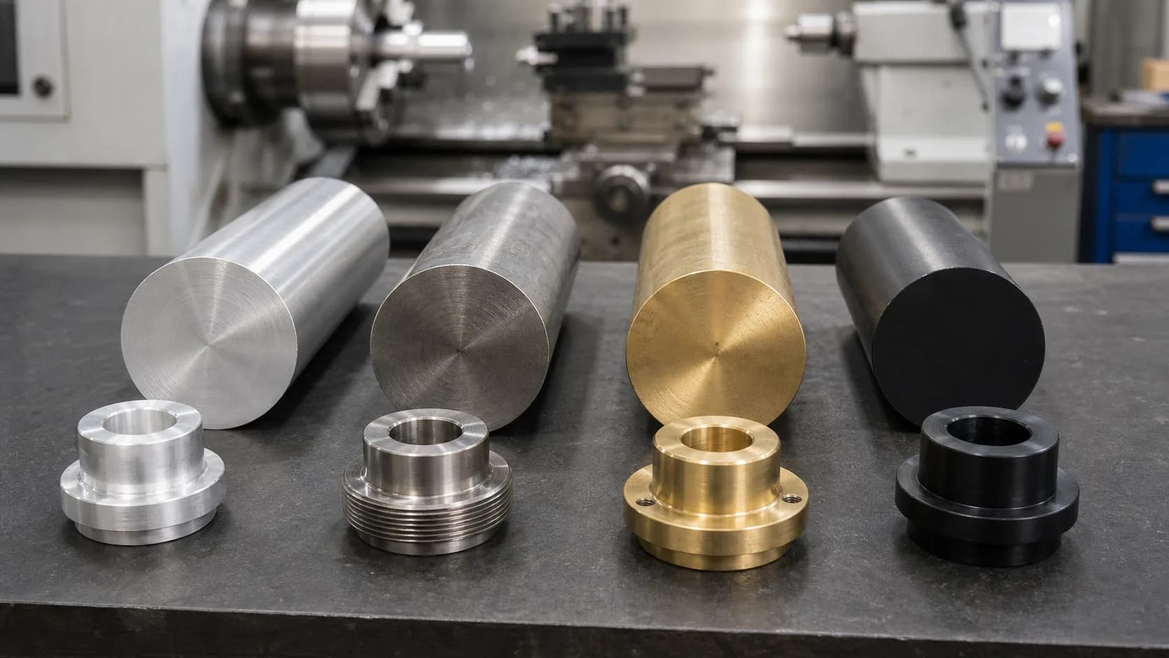
Material choice matters twice in turning: once for part function, and again for how the bar behaves in the cut. The best materials for turned parts are available as stable round stock, break chips predictably, and do not force the shop into heroic workholding or tool-life compromises. Use this section with the broader material selection guide when the part geometry is set but the alloy still is not.
| Material | Why it turns well | Where it is commonly used |
|---|---|---|
| 12L14 steel | One of the easiest steels to machine, with good chip break and excellent surface finish on turned features. | Pins, shafts, fittings, and general industrial hardware where corrosion resistance is not the primary driver. |
| 303 stainless steel | Free-machining stainless with good corrosion resistance and more predictable chip control than 304 stainless steel. | Shafts, valve components, and sensor hardware that need stainless behavior without the machining penalty of 304. |
| 17-4 PH stainless steel | Higher strength than 303 stainless steel, but it still machines well in the correct condition before final hardening. | High-load shafts, couplers, and wear parts where strength and corrosion resistance both matter. |
| 6061-T6 aluminum | Widely available in round bar, easy to machine, and good for lightweight turned parts. | Spacers, adapters, optical mounts, and enclosures with rotational geometry. |
| Acetal homopolymer (Delrin) | Stable, low-friction engineering plastic that turns cleanly and is commonly available as rod stock. | Bushings, rollers, wear components, and low-friction spacers. |
One practical rule engineers often miss
If the part will be quoted from bar stock, always ask whether the chosen alloy is routinely stocked in round sizes near your finished diameter. A theoretically good alloy can still be a poor turning choice if the shop must start from oversized billet, remove excessive material, or chase unstable chip control just to reach the final shape.
Tolerances and Surface Finish for Turned Parts
A tolerance is the acceptable variation around the nominal size, and turning is often chosen because it keeps OD and ID features naturally concentric. That does not mean every diameter should be held tightly. Use the CNC tolerances guide for a broader framework, but the table below is the right starting point for common turned features.
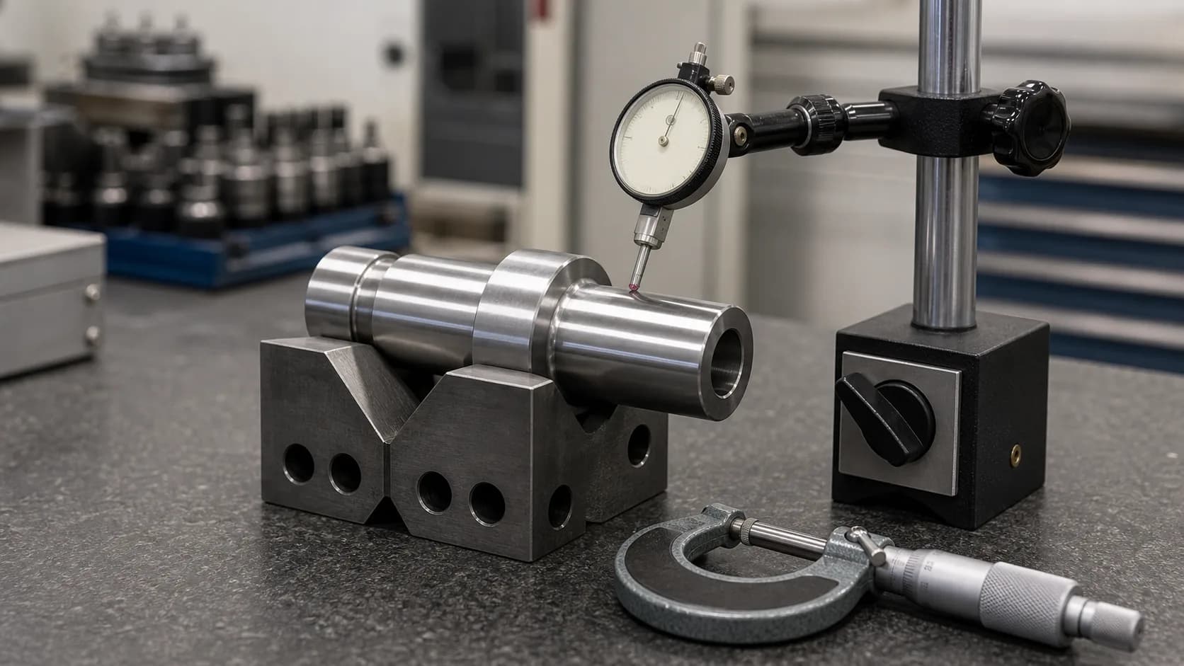
| Feature class | Typical range | What it means |
|---|---|---|
| General turned dimensions | +/-0.005 in. (+/-0.13 mm) | Good baseline for non-critical lengths, chamfers, and non-mating diameters. |
| Critical OD or ID after a finish pass | +/-0.001 in. (+/-0.025 mm) | Usually reserved for bearing seats, press fits, sealing diameters, or other function-driving features. |
| As-turned surface finish | 125-250 uin Ra (3.2-6.3 um Ra) | Common for roughing plus finishing on stable materials with standard tooling and sensible feed rates. |
| Fine finish on stable materials | 32-63 uin Ra (0.8-1.6 um Ra) | Usually needs a light finishing pass, sharp tooling, and a material that supports clean chip formation. |
Tolerance should follow function
A bearing seat, seal diameter, or press-fit journal may justify a tighter tolerance because the assembly literally depends on it. A cosmetic undercut or a clearance-only shoulder usually does not. Make the drawing tell the shop which surface controls function, or the quote will assume every diameter matters equally.
Surface finish is tied to tooling, feed, and material
A turned surface can look excellent and still miss a sealing requirement. If surface finish matters, specify it directly on the drawing and note whether the value applies to the bore, shaft, face, or groove. Otherwise the shop will assume standard as-machined finish and quote accordingly.
Design Rules for CNC Turning
Good turning DFM starts with one question: what feature really controls function? The answer tells you which diameters need tighter tolerance, which lengths can relax, and whether the part should stay on a lathe or move toward a more general CNC design guidelines workflow. The table below is a strong design-review checklist before you send the job into an RFQ package.
Keep the part rotational unless function says otherwise
Every off-axis feature moves the part away from a pure turning workflow and adds tooling, cycle time, or secondary operations.
Flag long slender parts early
Once unsupported length-to-diameter ratio climbs, deflection and chatter become the real design limit. Tailstocks, steady rests, or Swiss turning may be needed.
Specify thread reliefs and cutoff cleanup faces
Threads need runout space, and part-off leaves a witness that may require a finishing strategy on functional faces.
Use standard groove and tool widths when possible
Standard inserts are cheaper, easier to source, and less risky than custom narrow grooving tools.
Do not hold tight tolerance on non-functional lengths
Critical diameters drive fits. Many overall lengths only need a sensible general tolerance, not a premium inspection plan.
Match the RFQ package to the turned feature that matters
If concentricity, runout, or surface finish controls function, make that explicit in the drawing and note the inspection method in the RFQ.
RFQ checklist for turned parts
| If this matters | Put this in the RFQ |
|---|---|
| Fit-critical OD or ID | Identify the specific diameter, tolerance, finish requirement, and inspection method. |
| Long slender shaft | Call out finished length, diameter, straightness risk, and whether tailstock, steady rest, or Swiss turning is acceptable. |
| Live-tooled features | Mark cross-holes, flats, slots, and secondary-face features so the quote reflects the real machine route. |
| Inspection-sensitive assemblies | Attach the drawing and note whether the order needs CMM reporting, material certs, or other verification in the same package described in the manufacturing RFQ checklist. |
Frequently Asked Questions
What is CNC turning used for?
What parts are best for CNC turning?
How accurate is CNC turning?
When should I use Swiss turning instead of conventional CNC turning?
Can CNC turning make flats and cross-holes?
What materials are good for CNC turned parts?
Is CNC turning cheaper than CNC milling?
Related Resources
Need a CNC turning quote with the process route called out?
MakerStage supports CNC machining projects that combine turning, milling, and inspection planning in one RFQ flow. Upload your model and drawing to get a reviewed quote, process feedback, and CMM inspection options on request for fit-critical turned features.
Start a CNC turning quote