CNC Machining Copper Design Rules & Tolerances
Copper is one of the most challenging metals to machine well. Here is the complete DFM guide — built-up edge, chip control, speeds and feeds, tolerance limits, and design rules by alloy.
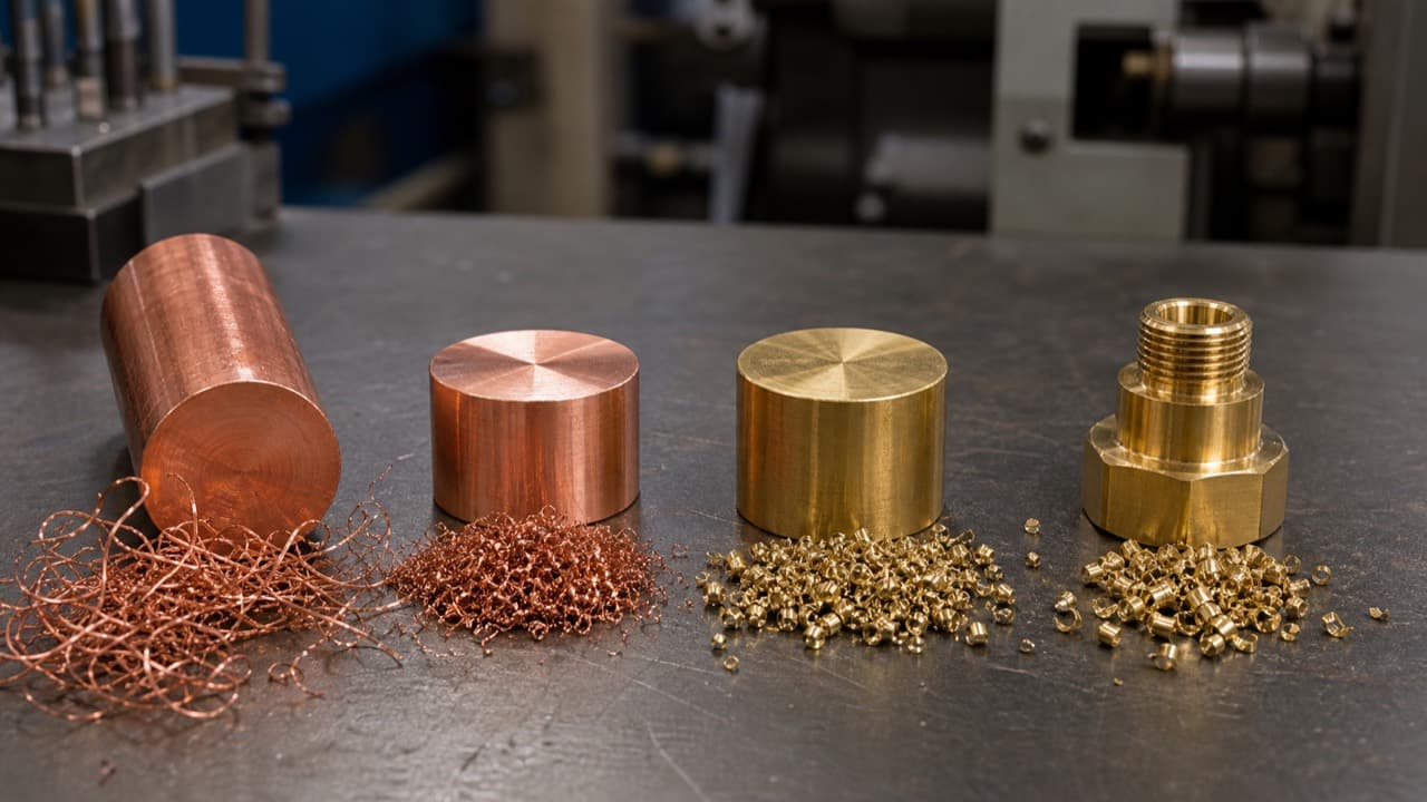
Alloy Choice Determines Whether Copper Is Cheap or Expensive to Machine
C360 free-cutting brass and pure copper (C110) are both “copper alloys” — but their machinability differs by 5×. A part that takes 3 minutes to turn in C360 takes 15 minutes in C110 with increased tool wear. This guide covers the mechanics of why, the exact parameters to use for each alloy, and the DFM rules that prevent the most common copper machining failures before the part hits the floor.
Why Pure Copper Is Challenging to Machine
Three mechanisms make pure copper difficult. Each has a specific engineering fix. Understand the root cause before choosing the remedy.
Built-Up Edge (BUE)
Root Cause
Copper is highly ductile and has strong affinity for most tool materials (carbide, HSS). At the cutting zone, the workpiece material welds to the tool face under the cutting temperature and pressure, forming a built-up edge. The BUE changes the effective tool geometry — it increases the actual depth of cut relative to programmed depth and creates a rough, torn surface finish rather than a clean shear surface.
Engineering Fix
Sharp, highly polished tooling with positive rake angle (8–12°). Uncoated carbide or PCD (polycrystalline diamond — a synthetic tool tip that resists copper adhesion far better than coated carbide). High surface speed (200+ sfm / 61+ m/min) so the cutting zone temperature is in a regime where BUE is less stable. Flood coolant with high-pressure application directed at the rake face.
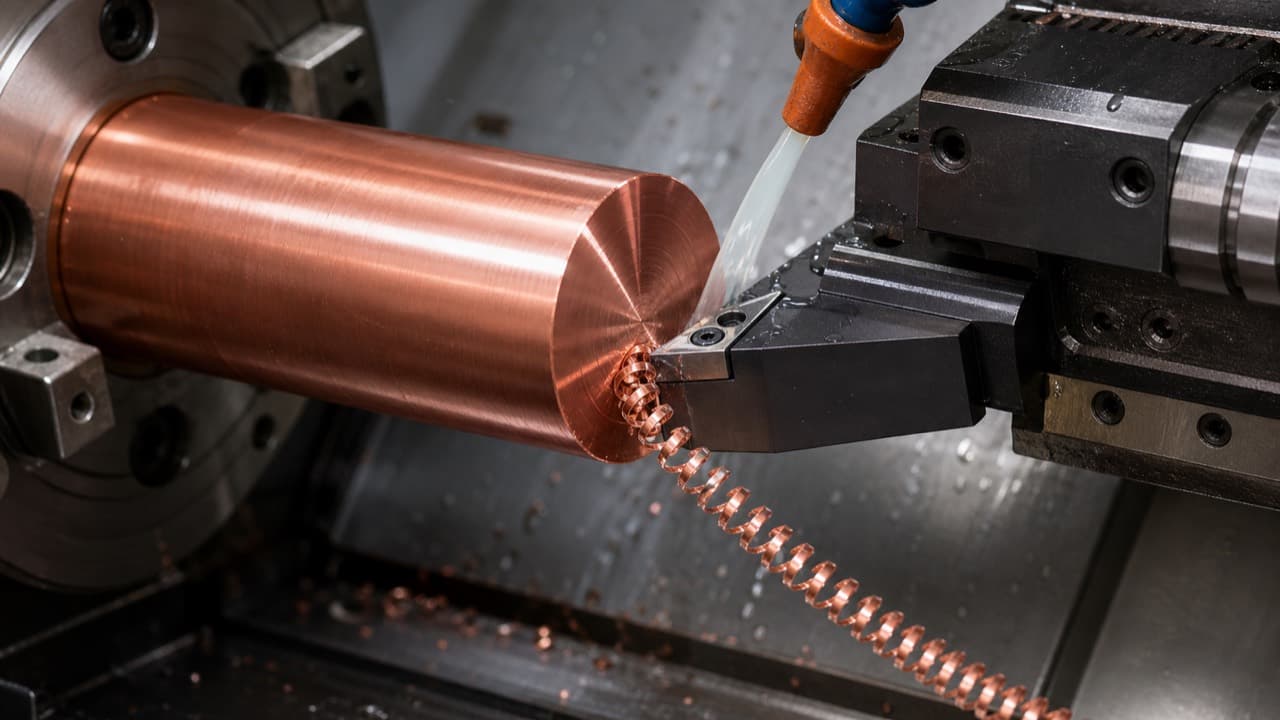
Long, Continuous Chips
Root Cause
Pure copper's high ductility means chips do not fracture — they flow continuously from the cutting zone, forming long, stringy coils that wrap around the workpiece, chuck jaws, and tool holder. In a production environment, this creates a chip management problem: the chips can damage the part surface, jam the tool path, and create a fire/entanglement hazard in the swarf collector.
Engineering Fix
Use chip-breaking insert geometry where nose radius permits. Increase feed rate to promote chip curl and break-off at the workpiece edge. Program periodic retracts on deep turning passes to break the chip manually. For milling, use climb milling (conventional vs. climb — chip thickness is largest at entry, promoting break-off).
Workholding Marking
Root Cause
Copper in the half-hard condition is approximately HRB 40–50. Standard steel chuck jaws (serrated) will indent the OD of copper workpieces under clamping force. For parts with tight OD tolerances or cosmetic finish requirements on clamped surfaces, this is a rejection cause.
Engineering Fix
Soft-jaw workholding (aluminum or brass-lined jaws bored to OD). Collet chuck with split collet for round bar stock. For milled copper, use step fixtures or sacrificial toe clamps. Never touch-off a datum surface directly with steel workholding on copper electrical contact parts.

Machinability by Copper Alloy
Machinability is rated relative to AISI B1112 free-machining steel at 100%. A higher rating means faster cycle time, lower tool wear, and better surface finish at equivalent parameters.
| Alloy | Machinability | Chip Form | BUE Risk | Recommended For | Avoid When |
|---|---|---|---|---|---|
| C36000 (Free-Cut Brass) | 100% | Short, discontinuous | None (Pb lubricates) | High-volume turning, connectors, fittings | RoHS applications (3% Pb content) |
| C26000 (Cartridge Brass) | 30% | Long, moderate | Low | Structural brass, formed parts, lower volumes | High-volume production (3× slower than C360) |
| C11000 (ETP Copper) | 20% | Long, continuous | High | Bus bars, electrical contacts with conductivity req. | High-volume turned fittings (use C360 instead) |
| C10100 (OFHC Copper) | 20% | Long, continuous | High | Parts requiring H₂ embrittlement resistance | Anywhere C110 works — pay premium only when justified |
Speeds, Feeds, and Tool Geometry
Starting parameters for CNC turning with uncoated carbide. Adjust based on machine rigidity, depth of cut, and part geometry. For PCD tooling, surface speeds can be increased 50–100%.
| Parameter | C101 / C110 | C260 | C360 | Notes |
|---|---|---|---|---|
| Surface speed (carbide) | 200–350 sfm (61–107 m/min) | 350–500 sfm (107–152 m/min) | 500–800 sfm (152–244 m/min) | Higher speed reduces BUE on pure copper |
| Feed rate, in./rev (ipr) | 0.003–0.006 | 0.004–0.008 | 0.006–0.012 | Higher feed promotes chip break-off |
| Depth of cut (roughing) | 0.050–0.100 in | 0.075–0.150 in | 0.100–0.200 in | Reduce on finishing passes |
| Depth of cut (finishing) | 0.005–0.010 in | 0.005–0.010 in | 0.010–0.020 in | Spring pass recommended for final OD |
| Rake angle (insert) | +8° to +12° | +5° to +10° | +5° to +8° | Positive rake critical for pure copper |
| Tool material | Uncoated carbide or PCD | Uncoated carbide | Uncoated carbide | Avoid coated inserts on pure copper |
| Coolant | Flood required | Flood recommended | Flood recommended | High-concentration (8–10%) water-soluble |
| Thread tapping speed | 50–80 sfm (15–24 m/min) | 80–120 sfm (24–37 m/min) | 100–150 sfm (30–46 m/min) | Use sulphurized oil for pure copper tapping |
Worked Example: Converting SFM to RPM
Formula: RPM = (SFM × 3.82) ÷ D, where D is the workpiece diameter in inches.
Example: Turning a 1.5 in. (38.1 mm) diameter C110 bar at 300 SFM (91 m/min):
RPM = (300 × 3.82) ÷ 1.5 = 764 RPM
For a 0.5 in. (12.7 mm) bar at the same SFM: RPM = 2,292. Smaller diameters require higher RPM to maintain the same surface speed — use constant surface speed (CSS) mode on your CNC controller when available, and it will adjust RPM automatically as the diameter changes during facing or profiling cuts.
Get a DFM-Reviewed Quote for Your Copper Part
MakerStage machines all four copper alloys — C101, C110, C260, and C360. Upload your CAD file and our team will review geometry, flag features that drive cost on copper, and include material availability in the quote review.
Get a Copper CNC QuoteAchievable Tolerances and Surface Finish
Tolerance capability on copper is comparable to aluminum in production conditions — with the caveats that workholding pressure must be controlled and pure copper requires sharper tooling. Surface roughness is measured as Ra (arithmetic average roughness) — the mean of all peak-to-valley deviations from the centerline across the measurement length. Lower Ra means smoother: Ra 32 µin. (0.8 um) is a standard machined finish; Ra 16 µin. (0.4 um) approaches a polished appearance.
| Feature | C360 (Brass) | C110 / C101 (Pure Cu) | Notes |
|---|---|---|---|
| Turned OD (standard) | ±0.001 in (±0.025 mm) | ±0.001 in (±0.025 mm) | Achievable with good carbide tooling |
| Turned OD (precision) | ±0.0005 in (±0.013 mm) | ±0.0005 in (±0.013 mm) | Requires PCD or freshly sharpened carbide |
| Bored ID (standard) | ±0.001 in (±0.025 mm) | ±0.001 in (±0.025 mm) | Single-point boring recommended for precision |
| Milled pocket (standard) | ±0.002 in (±0.050 mm) | ±0.002 in (±0.050 mm) | Climb milling preferred |
| Flatness | ±0.001 in/in | ±0.002 in/in | Pure copper requires stress-relief fixturing |
| Thread fit (tapped) | 6H (standard) | 6H (standard) | Use sulphurized oil for pure copper |
| Surface finish (turning) | Ra 32–63 µin (0.8–1.6 um) | Ra 32–63 µin (0.8–1.6 um) with carbide | PCD achieves Ra 16 µin (0.4 um) on pure copper |
| Surface finish (milling) | Ra 32–63 µin (0.8–1.6 um) | Ra 63–125 µin (1.6–3.2 um) | Milling pure copper is more challenging |
DFM Rules for Copper Parts
Eight rules that reduce cost, improve yield, and prevent the most common copper machining quality issues.
Specify C360 unless conductivity or embrittlement resistance requires C110/C101
If your part does not need >26% IACS conductivity, C360 is 5× more machinable, cheaper per pound, and produces dramatically better surface finish. Misspecifying C110 where C360 would work is the most common copper DFM error.
Avoid thin walls (<0.040 in / 1 mm) on pure copper parts
Pure copper's low yield strength in the annealed condition means thin walls deform under cutting forces. If thin walls are required, machine from half-hard (H02) stock and relieve clamping stress with a spring-pass finishing cut.
Chamfer all sharp edges — copper burrs are tenacious
Copper burrs are ductile and difficult to remove cleanly. Add 0.010–0.020 in (45°) chamfers on all external edges on the drawing. This converts a deburring operation into a controlled chamfer cut, which is faster and more consistent.
Limit slot aspect ratio to 3:1 depth-to-width on pure copper
Deep, narrow slots in pure copper require multiple depth-of-cut passes and are prone to burring on the side walls. C360 can be slotted to 5:1 aspect ratio cleanly; pure copper should be limited to 3:1 without special tooling.
Specify the surface finish Ra on the drawing, not just "machine finish"
"Machine finish" on copper is ambiguous — it can mean anything from Ra 250 µin (6.3 um) for a rough pass to Ra 32 µin (0.8 um) for a good turning pass. Specify the required Ra explicitly. If cosmetic appearance matters, also call out the direction of lay.
For C110/C101 ODs requiring tight tolerance, always include a spring-pass note
A spring pass (same depth of cut, no incremental infeed) on the final turning pass removes the elastic deflection of the previous pass and brings the OD to the intended dimension. For pure copper, this improves tolerance capability by ~50% without requiring a tighter program tolerance.
Design through-holes with a minimum diameter of 0.050 in (1.27 mm)
Drilled holes smaller than 0.050 in in pure copper require very sharp, carefully runout-checked drills and risk drill breakage in the ductile material. Below 0.040 in, use EDM if the copper must be C110/C101; or use C360 which drills more cleanly.
Do not anodize copper — specify electroless nickel, silver, or tin plating
Anodizing is an aluminum-specific process. Copper is plated, not anodized. Specify the appropriate copper-compatible surface finish. See the copper surface finishes guide for the full decision matrix.
Frequently Asked Questions
Ready to Machine Your Copper Part?
Upload your CAD file for a copper CNC quote. C101, C110, C260, and C360 quotes can include DFM feedback before production.
Get a Copper CNC Quote