Types of Holes in CNC Machining
A hole is more than an empty cylinder in your part. In practice, the hole type determines how the part is machined, how it is inspected, how the fastener or pin seats, and how much the feature costs. If you understand through holes, blind holes, counterbores, countersinks, spotfaces, reamed holes, and tapped holes, you will write cleaner drawings and avoid a large share of preventable shop questions.

What counts as a hole in CNC machining?
A hole is any internal cylindrical or near-cylindrical feature made to create clearance, thread engagement, location, fluid flow, or a seating surface. The simplest split is between a through hole and a blind hole. That sounds basic, but it is the first question a machinist asks because it changes chip evacuation, tool access, inspection strategy, and cost.

A through hole exits the other side of the part. Chips have somewhere to go, coolant can flush the cut, and the shop usually reaches the size faster. That is why a through hole is the default choice whenever the part function allows it.
A blind hole stops inside the material. The part may need that geometry because the backside is visible, sealed, or structurally important. In practice, blind holes are harder to drill cleanly because the chips cannot escape straight through and the tool tip leaves a cone-shaped bottom instead of a flat floor.
If you are new to machining, start with the question: does this hole just need to let something pass through, or does it need to locate, seat, or retain something precisely? If it only needs clearance, standard drilling is often enough. If the hole controls a fit or datum relationship, you will likely move into the territory covered by the CNC tolerances guide and the true position guide.
For broader process context, this article works as a spoke off our what is CNC machining overview. If you are already preparing a manufacturable part package, the next practical step is a manufacturing RFQ checklist.
The hole types you will see on real drawings
Each hole type solves a different problem. The most reliable way to think about them is by function: pass-through, seat a fastener, control a fit, or create thread engagement.

| Hole type | Geometry | Common use | Process | Typical size control | Relative cost |
|---|---|---|---|---|---|
| Through hole | Breaks out the far side of the part | Clearance holes, dowel clearance, fluid passages | Drill first; ream or bore if tighter size control is needed | Drilled: about +/-0.003 to +/-0.005 in. (+/-0.08 to +/-0.13 mm) | Lowest |
| Blind hole | Stops before the far face | Tapped features, pockets, hidden fasteners | Drill with extra tip clearance; may need peck cycles | Similar size tolerance to drilling, but depth control matters separately | Low to medium |
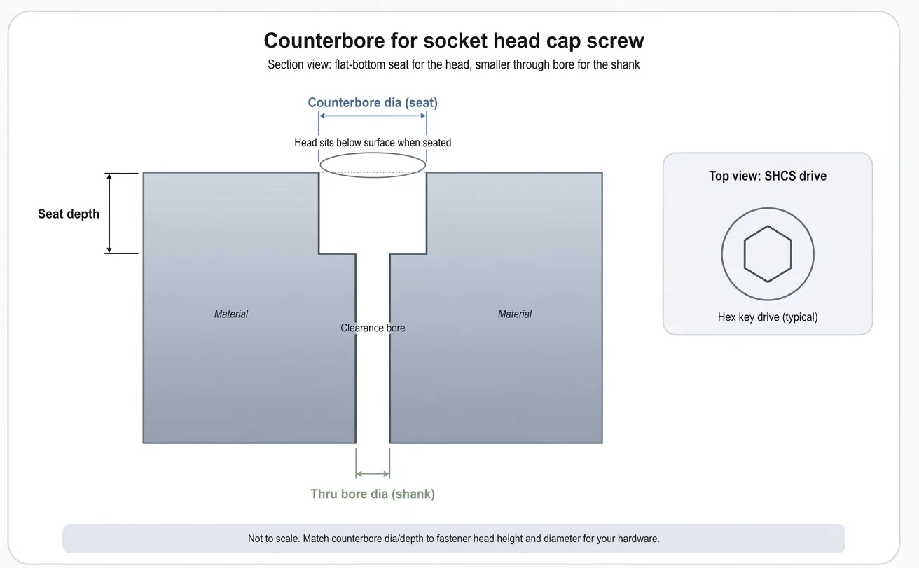
| ⌴Counterbore | Flat-bottom larger diameter above a smaller hole | Socket head cap screw seating | Drill plus counterbore tool or end mill interpolation | Seat diameter often held to about +/-0.002 to +/-0.005 in. (+/-0.05 to +/-0.13 mm) | Medium |
| ⌵Countersink | Conical entrance, commonly 82 deg, 90 deg, or 100 deg (per ASME B18.6.3 / ISO 10642) | Flat-head screws, burr break, chamfered entrances | Drill plus countersink tool | Diameter and included angle both matter | Low to medium |
| Spotface | Shallow flat seat with minimum material removal | Fastener seating on rough or cast surfaces | Face only the contact land, not a deep pocket | Usually standard machining tolerance unless seat flatness is critical | Low |
| Reamed hole | Finished cylindrical hole with improved size and finish | Dowel pins, slip fits, bearing fits | Drill undersize, then ream | Often about +/-0.0005 to +/-0.001 in. (+/-0.013 to +/-0.025 mm) | Medium to high |
| Tapped hole | Internal thread cut into a drilled hole | Screw retention without a nut | Drill tap size first, then tap or thread mill | Controlled by thread class and thread depth rather than simple hole diameter | Medium |
| Cross-drilled hole | Intersects another bore or shaft feature | Pins, lubrication passages, venting | Secondary setup or indexed operation | Position often dominates over diameter | Medium to high |
Through holes
The default choice for cost and reliability. If a screw, pin, or passage can break through the part, use that freedom. The drill cuts faster, chips evacuate better, and inspection is simpler.
Blind holes
Use them only when the backside matters. The functional depth is never the same as the total drilled depth, because the tool tip is conical and needs extra clearance.
Counterbores and spotfaces
These create flat seating lands. A counterbore is deeper and usually hides a screw head. A spotface is shallow and mainly cleans up a flat seat.
Countersinks
These are conical entrances. They match flat-head screws or create a controlled chamfer. Always specify the included angle, not only the top diameter.
Reamed holes exist because drilling is fast, not exact. A reamer follows a pre-drilled hole and removes a small amount of material to improve diameter repeatability and finish. That is why dowel and pin holes often specify a reamed finish.
Tapped holes combine size and thread geometry. The starting diameter matters because it sets the thread engagement, but the acceptance criterion is the finished thread class and depth. If you need a deeper thread design treatment, continue into the tapped hole design guide.
Cross-drilled and intersecting holes deserve a mental flag. They are not automatically difficult, but once a hole breaks into another bore, burr control, wall support, and fixture access matter more than they do on a simple plate.
Drilling is the start, not the whole story
The machining process defines what size, roundness, finish, and cost you should expect. A common design mistake is to ask for a hole requirement that implies reaming or boring, while mentally pricing it as a simple drilled feature.

| Process | Best for | Characteristics | Typical accuracy | Surface result | Relative cost |
|---|---|---|---|---|---|
| Drilling | General-purpose hole creation | Fastest way to make most holes | About +/-0.003 to +/-0.005 in. (+/-0.08 to +/-0.13 mm) | Typically 63-125 uin. Ra (1.6-3.2 um Ra). Good for general clearance or pre-finish features | 1.0x baseline |
| Boring | Correct hole location, roundness, and size after drilling | Better control on larger or tighter holes | Often about +/-0.001 to +/-0.002 in. (+/-0.025 to +/-0.05 mm) | Typically 32-63 uin. Ra (0.8-1.6 um Ra). Better cylindricity than drilling alone | 1.5x to 2.5x |
| Reaming | Finish a drilled hole to a tighter diameter | Best for pin holes and light press/slip fits | Often about +/-0.0005 to +/-0.001 in. (+/-0.013 to +/-0.025 mm) | Typically 16-63 uin. Ra (0.4-1.6 um Ra). Improved surface finish and size repeatability | 1.2x to 2.5x |
| Tapping | Create internal threads | Best for standard threads and moderate depth | Thread class controls acceptance, not simple diameter | Functional thread, not a bearing bore finish | 1.3x to 2.0x vs plain drilled hole |
| Thread milling | Threads in harder materials, larger threads, or high-value parts | Adjustable pitch diameter in program | High control when programmed and tooled correctly | Good thread form with lower breakage risk | 2.0x to 4.0x vs plain drilled hole |
Drilling
Best for most clearance holes and as the first step before reaming or tapping. Fast, cheap, and widely available.
Boring or interpolation
Better when size, concentricity, and location all matter, especially on larger bores or fit-critical features.
Reaming
Best when you already have a good pilot hole and need a more repeatable final diameter for a pin or slip fit.
Hole tolerance controls cost faster than most engineers expect
A tolerance is the allowed variation band around the nominal size. The tighter that band becomes, the less the shop can rely on a simple drilled feature and the more it moves into finishing operations and inspection.

Standard drilling is often enough for clearance. If a bolt just needs to pass through, spending for a reamed-hole tolerance usually does not improve the assembly. It only adds cycle time and inspection work.
Fits matter when the hole locates or supports something. Dowel pins, bearing bores, and close-fit shafts depend on a controlled diameter. That is when the drawing should push the process toward reaming, boring, or a more explicit fit class.
In ISO fit language (per ISO 286), an H7 hole is a common general-purpose location fit because the lower deviation is zero and the tolerance band sits above nominal. You do not need to memorize every fit table to use fit callouts well, but you do need to know that fit language implies a finishing process, not a casual drilled feature.
| Functional need | Recommended method | Why |
|---|---|---|
| Clearance for a bolt | Drill to standard clearance size | Fast and cheap; hole size is not carrying a precision fit |
| Dowel pin location | Drill undersize, then ream | Pin holes need predictable diameter and roundness |
| Bearing housing bore | Bore or interpolate, then ream only if geometry allows | Housing bores need size plus location and cylindricity control |
| Threaded fastener retention | Drill tap size, then tap or thread mill | The threaded feature matters more than the pilot diameter alone |
Worked example: a bearing bore is not a clearance hole
Suppose your nominal bore is 0.7500 in. (19.050 mm) for a light press-fit bearing outer ring. A typical light press-fit bore might be held to +0.0000/-0.0005 in. (+0.000/-0.013 mm). If you call out a standard drilled hole, the size spread and roundness are usually too loose for reliable seating. Drilling alone can vary by +/-0.003 in. or more, six times wider than the required band. In practice, that tolerance rules out drilling entirely and pushes the shop toward boring or interpolation followed by inspection with a bore gage or CMM.
A good hole callout tells manufacturing exactly what matters
Define the feature, explain why it exists, and then state the numbers. A machinist should not have to guess whether your hole needs a flat seat, a conical seat, a thread, or a position tolerance.

Through or blind
If the hole is blind, state the depth. If only a minimum depth matters, write that clearly. Do not assume the shop will infer the usable depth from the nominal drill depth.
Counterbore or countersink
State the seat diameter and depth for a counterbore. For a countersink, state the major diameter and included angle. Diameter without angle is incomplete.
Threaded holes
State thread size, pitch or series, class, and depth when the hole is blind (per ASME Y14.6 / ISO 6410). Thread depth and drill depth may differ by several pitches.
Callout mistake to avoid
If the assembly depends on where the hole is, a size callout alone is not enough. Size answers "how big is the feature?" Positional tolerance (per ASME Y14.5-2018 / ISO 1101) answers "where is the feature allowed to exist relative to the datums?" That distinction is why hole patterns often pair a diameter note with a GD&T position frame.
DFM rules that keep holes manufacturable
Hole DFM is mostly about keeping the process standard: standard drills, reasonable depth, realistic tolerance, and enough room for chips and tools to work.

Prefer through holes over blind holes when function allows. Through holes are easier to drill, easier to inspect, and less likely to pack chips.
For standard twist drilling, keep depth near 4x diameter when possible. Going deeper is achievable, but cycle time and chip-evacuation risk increase quickly.
In blind holes, add drill-tip clearance below the functional depth. A 118 deg or 135 deg drill point does not produce a flat bottom.
Use standard drill sizes before custom decimal diameters. Standard tooling is cheaper and easier to replace.
Do not tighten a hole tolerance unless the assembly actually needs it. Many clearance holes work reliably at standard drill tolerance.
Call out thread depth and drill depth separately for blind tapped holes. They are not the same number.
Leave at least 1x the hole diameter as wall thickness between adjacent holes and between a hole and the part edge. For thin-wall aluminum, 0.060 in. (1.5 mm) minimum is typical to avoid breakout, distortion, or weak clamp lands.
If location matters more than size, apply positional tolerance thoughtfully instead of over-tightening the diameter.
Practical rule of thumb
Start with a standard drilled through hole unless the part function proves you need something more. Then add complexity one step at a time: blind depth, seat geometry, tighter size control, thread, or positional tolerance. That sequence keeps your drawing matched to the real manufacturing need instead of accumulating expensive defaults.
Quick decision rule
- Clearance only: use a standard drilled hole if assembly allows.
- Fastener seat: add a counterbore, countersink, or spotface.
- Precision fit: plan on reaming or boring.
- Retention: use a tapped hole or an insert strategy.
- Location critical: size may be secondary to positional tolerance.
Need a manufacturability check on your hole pattern?
If your part has fit-critical bores, tapped blind holes, or hole patterns tied to datums, our CNC machining team can review the geometry during quoting. MakerStage offers free DFM review on every RFQ, with CMM inspection available on request for parts where hole location and size matter.
Upload a Part for DFM ReviewCommon hole mistakes engineers make
These mistakes usually come from treating every hole as if it were just a diameter on a drawing. Function, process, and inspection all matter.

Using a reamed-hole tolerance on every drilled hole
This forces the shop into a slower finishing process even when the assembly only needed a bolt clearance feature.
Forgetting that blind-hole depth is measured to the full drill depth
The usable cylindrical portion is shorter than the nominal drill depth because the drill tip is conical.
Calling out a countersink without the included angle
A diameter alone is ambiguous because 82 deg, 90 deg, and 100 deg countersinks produce different top diameters at the same depth.
Specifying non-standard decimal thread pilot sizes
The machinist may need a special tool or an extra interpolation step when a standard tap drill would have done the job.
Assuming hole size alone guarantees assembly fit
A hole can measure in tolerance and still fail the assembly if its position relative to datums is wrong.
Ignoring burrs and entry chamfers
Even a correct diameter can scratch mating parts, damage threads, or make fastener insertion inconsistent.

Frequently Asked Questions
Related Resources
Ready to quote a part with critical holes or threads?
If your design depends on fit-critical bores, tapped holes, or true-position-controlled patterns, send the drawing through our online RFQ flow. MakerStage supports custom CNC machining with free DFM review, and can provide CMM inspection on request when hole geometry is part of the acceptance criteria.
Get Free Quote Fast