Prototype to Production: The Manufacturing Process Scaling Roadmap
A visual guide to transitioning from 3D printing through CNC machining, urethane casting, and sheet metal to injection molding — with the cost crossover points and decision triggers at each stage.
View the scaling roadmap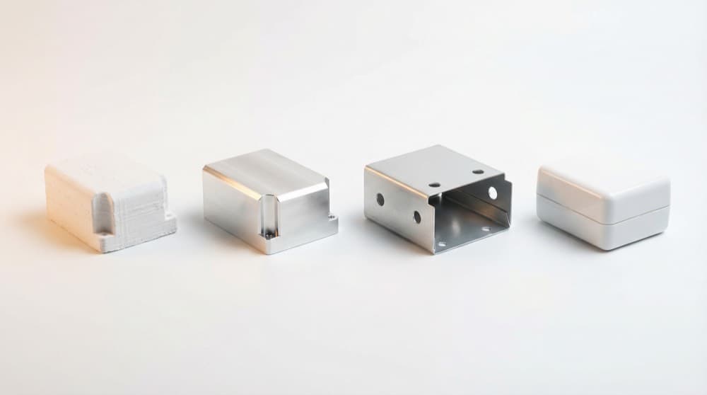
The Four Phases of Hardware Product Development
Before you choose a manufacturing process, you need to know where you are in the development lifecycle. The same decision — 3D printing vs. CNC vs. injection molding — looks completely different at EVT than at DVT, and entirely different again if you're still in the design or engineering loop.
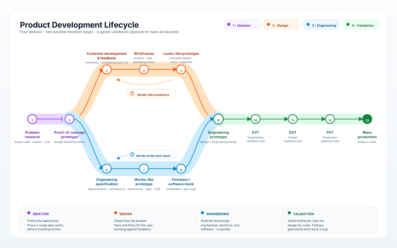
Ideation
Prove that a real problem exists and that your approach is directionally correct — before investing in design or engineering.
⏱ 2–6 weeks
Stages
- 1Problem research— User interviews, market sizing, competitor teardowns. Output: evidence that real users have this problem and would pay to solve it.
- 2Proof-of-concept prototype— Rough demo built to answer "can this work?" — not "should we build this?" FDM prints, off-the-shelf electronics, zip ties acceptable.
Exit signal: You have direct evidence (not assumptions) of willingness to pay, and the PoC demonstrates the core mechanism works.
Watch out: Skipping problem research is the leading cause of hardware product failure. Most teams that build the wrong product had the right engineering — they validated the solution before validating the problem.
Design Loop
Validate that the product's form, UX, and packaging solve the user's problem in the way they expect — before finalizing any engineering.
⏱ 4–12 weeks per iteration; typically 2–4 loops
Stages
- 1Customer development & feedback— Structured sessions where real users interact with the current concept. Goal: surface assumptions and confusions in the UX or physical form.
- 2Wireframes (product / app / packaging)— Low-cost layout validation — screen flows, button placement, unboxing sequence, physical interface layout. Paper or Figma for software; foam or cardboard for hardware form.
- 3Looks-like prototype— Industrial design finalized: form, color, material, finish (CMF). Built with SLA 3D printing ($8–$40/part) or urethane casting. Surfaces are production-representative; internals are hollow or mocked.
Exit signal: Users interact with the looks-like prototype without coaching, complete their primary task, and can describe what the product does without prompting.
Watch out: This loop runs in parallel with the engineering loop — design and engineering teams should agree on interface constraints (outer envelope, key mounting points, display cutouts) and then iterate independently. Serializing the loops adds 3–6 months to the timeline.
Engineering Loop
Prove the technology works — mechanically, electronically, and in firmware — under representative operating conditions.
⏱ 6–16 weeks per iteration; typically 2–3 loops
Stages
- 1Engineering specification— System architecture, BOM, interface definitions, power budget, tolerance stack-up, regulatory requirements (FCC, UL, CE). Output: a document the team can build to without daily clarification.
- 2Works-like prototype— Functional tech stack at relaxed tolerances and rough finish. CNC machined structural members, prototype PCBs (2-layer, hand-soldered), off-the-shelf connectors. Cost is 5–20× higher than production — that's normal.
- 3Firmware / software stack— Embedded firmware, communication protocols (BLE, Wi-Fi, CAN), mobile or cloud app integration. Typically reaches feature-complete in parallel with the second or third works-like iteration.
Exit signal: The works-like prototype passes functional tests (power draw, thermal, RF, load, sensor accuracy) under representative operating conditions. No hardware blockers remain.
Watch out: Works-like prototypes intentionally use CNC stand-ins for injection-molded parts and prototype PCBs — cost and lead time don't reflect production. A works-like prototype that costs $2,000 to build may become a $15 production part.
Validation
De-risk the design and the manufacturing process for full-rate production through three sequential gates, each with explicit pass/fail criteria.
⏱ 12–40 weeks across all gates
Stages
- 1EVT — Engineering Validation Test (1–25 units)— Merged design + engineering prototype. Proves form, fit, and basic function. Manufacturing process: FDM/SLA 3D printing + selective CNC.
- 2DVT — Design Validation Test (25–200 units)— Real-world reliability, environmental, and compliance testing. Manufacturing: SLS/MJF for plastics, CNC for metals, urethane casting as bridge.
- 3PVT — Production Validation Test (200–2,000 units)— Also called Pilot or Pre-Production. Proves the manufacturing process works at rate — yield, cycle time, quality. First use of production or bridge tooling.
- 4Mass production (2,000+ units)— Full-rate production with optimized per-part economics. Production injection molds, CNC at volume, progressive-die sheet metal.
Exit signal: Each gate has explicit pass/fail criteria agreed before the build. Failing a gate returns the product to the relevant loop — design failure back to the design loop, supply chain failure to the engineering loop.
Watch out: The validation pipeline appears sequential but often runs in parallel for different subsystems. An enclosure may be at PVT while the main PCB is still at DVT. Map each subsystem separately.
| Phase | Typical duration | Output | Primary prototyping method | When to engage MakerStage |
|---|---|---|---|---|
| Ideation | 2–6 wks | Proof-of-concept prototype | FDM 3D printing, off-the-shelf components | Not yet — keep spend low until problem is validated |
| Design loop | 4–12 wks/iter | Looks-like prototype | SLA 3D printing, urethane casting | SLA or urethane quotes for CMF models ($8–$75/part) |
| Engineering loop | 6–16 wks/iter | Works-like prototype + firmware | CNC machining (metals), prototype PCBs | CNC quotes + free DFM review for production-intent parts |
| Validation (EVT→PVT) | 12–40 wks total | Production-qualified design | CNC, SLS/MJF, sheet metal, injection molding | Full manufacturing partnership — choose production supplier by DVT |
How design and engineering loops converge
The two loops run independently, syncing on interface constraints (outer envelope, mounting points, display cutouts, power connectors). Convergence happens when a single physical prototype — the engineering prototype — passes basic functional tests AND satisfies the industrial design brief. That prototype is the entry point to EVT. The rest of this guide covers how to select manufacturing processes at each validation stage.
Don't serialize the design and engineering loops
A common mistake: the engineering team waits for "final" industrial design before starting PCB layout and mechanical design. In practice, both loops run in parallel with agreed interface constraints — design can update CMF and form factor without blocking engineering, and engineering can iterate on PCB layout and firmware without blocking design. Teams that serialize these loops add 3–6 months to the development timeline with no reduction in risk.
The Six Manufacturing Processes
Each process has a volume sweet spot and cost structure. The tolerance column lists the main variables that control capability—not a universal drawing tolerance. Confirm the final requirement with the supplier for your exact part and inspection plan.
| Process | Sweet Spot | Lead Time | Tolerances | Per-Part Cost | Tooling Cost |
|---|---|---|---|---|---|
| FDM 3D Printing | 1–25 parts | 1–3 days | Machine-, material-, axis-, and geometry-dependent | $5–$50 | $0 |
| SLA / SLS / MJF | 1–200 parts | 2–5 days | SLA: resin-, system-, and geometry-dependent; SLS/MJF: material-, system-, orientation-, and size-dependent | $8–$80 | $0 |
| CNC Machining | 1–5,000 parts | 3–10 days | Feature-, setup-, material-, and inspection-dependent | $50–$500 | $0–$500 (fixtures) |
| Urethane Casting | 10–200 parts | 5–15 days | Resin-, geometry-, shrinkage-, and post-cure-dependent | $15–$75 | $500–$3,000 (silicone mold) |
| Sheet Metal | 10–100,000+ parts | 5–15 days | Material-, temper-, thickness-, bend/tooling-, and datum-dependent | $10–$200 | $0–$5,000 (bending tools, fixtures) |
| Injection Molding | 500–1,000,000+ parts | 4–12 weeks (incl. tooling) | Nominal-size-, resin-, geometry-, and process-dependent | $0.10–$5 | $2,000–$200,000+ |
Cost ranges assume a palm-sized part (~4" × 3" × 1.5") with moderate complexity. Actual costs vary by geometry, material, and requirements. Tolerance guidance names the factors you must define before a supplier can commit to a drawing requirement.
Already familiar with these processes?
Deep-dive guides: CNC Machining | 3D Printing | Sheet Metal | Injection Molding | 3D Printing vs CNC
The Process Scaling Roadmap
This chart shows where each manufacturing process is usually the strongest fit by annual volume. Each row keeps its process color. Solid bars mark the process sweet spot: the range where cost, lead time, and manufacturability usually line up best. Faded bars mean the process can work, but another process often wins economically.
How to read this chart: Follow a horizontal row to see when a process enters and exits its sweet spot as your volume grows. Follow a vertical column to see which processes compete at a given volume tier. Most products use 2–3 processes simultaneously (e.g., CNC for metal parts + injection molding for plastic parts).
One supplier from prototype through production
MakerStage covers CNC machining, 3D printing (FDM, SLA, SLS, MJF, DMLS), and sheet metal fabrication — so you can scale from 1 to 10,000+ parts without switching vendors. Every order includes free DFM feedback to prepare your design for the next volume stage.
Get a Quote for Your Current StageStage-by-Stage Breakdown
What processes to use at each product development stage — from first concept through full-rate production.
Prove the concept works. Validate form, fit, and basic function.
Recommended Processes
Fastest iteration cycle. Print overnight, test in the morning, redesign by afternoon. $5–30/part means you can afford to throw parts away.
When you need smooth surfaces for stakeholder demos or fine features that FDM can't resolve.
Only for parts that must be metal for functional testing — load-bearing brackets, thermal interfaces, or press-fit features.
Pro Tip
At this stage, don't over-specify tolerances or finishes. General tolerances (±0.010″) and as-printed surfaces are fine. Every tight callout you add increases cost without adding learning.
Validate the design under real-world conditions. Run reliability, environmental, and compliance tests.
Recommended Processes
Do not assume that all SLS or MJF nylon properties are isotropic. Performance depends on the material, machine, build orientation, process settings, powder history, conditioning, and test method. Use supplier data to plan tests, then validate production-intent parts.
Full material properties from wrought stock. The DVT parts ARE the material you'll use in production — so your test data directly translates.
When you need 50–100 plastic parts that simulate injection-molded properties (e.g., ABS-like, PP-like) without tooling investment.
Sheet-metal translation risk can be low when production keeps the same alloy, temper, thickness, supplier, tooling, forming sequence, grain direction, finish, and inspection plan. Revalidate critical dimensions and performance when you move from laser cutting and press-brake forming to stamping, progressive dies, or other production tooling.
Pro Tip
DVT is where your DFM review matters most. The design you validate here is the design you'll tool for production. Catch issues now — a $200 CNC part revision is cheap; a $15,000 mold revision is not.
Prove your supply chain works. Build at rate, test yield and quality, ship to early customers or beta testers.
Recommended Processes
Still cost-effective at 200–2,000 units for some metal parts. CNC usually avoids production-mold cost, but a design change is not free: it can require CAM updates, new fixtures or soft jaws, first-article inspection, requalification, and scrap.
Aluminum molds ($2K–$15K) produce 1,000–5,000 parts with production-representative properties. 3–5 week lead time vs. 8–12 weeks for production steel.
Low-volume production can keep the DVT laser-cut and press-brake process. If production changes to progressive dies, stamping, automated bending, or different tooling, revalidate critical dimensions, springback, and functional performance.
If your bridge mold isn't ready yet, urethane casting covers the gap for 50–200 units while tooling is in progress.
Pro Tip
Lock your drawing revisions before cutting bridge tooling. Aluminum molds can handle minor revisions (adding a feature), but relocating a gate or changing wall thickness means a new mold.
Deliver at rate with stable cost, quality, and lead time. Optimize per-part economics.
Recommended Processes
Steel molds (P20 or H13) rated for 100K–1M+ shots. Per-part cost drops to $0.10–$2.00. Multi-cavity molds can double or quadruple throughput.
Still the right process for metal parts requiring tight tolerances (±0.001″), machined datums, or exotic alloys that can't be cast or formed.
At 10K+ units, progressive dies and automated bending cells reduce per-part cost by 30–60% vs. prototype-stage laser-cut parts.
Pro Tip
Don't jump to multi-cavity molds on day one. Start with a single-cavity production mold. Once demand stabilizes and you've confirmed the design, invest in multi-cavity (2x tooling cost, but 2–4x throughput and 25–40% lower per-part cost).
Cost Crossover Points
These are quote-dependent decision points for changing processes, plus the technical or economic signal that can trigger each move.
| Transition | Crossover Volume | Cost Driver | Decision Signal |
|---|---|---|---|
| 3D Printing → CNC | Quote-specific; often performance-led | CNC avoids hard-mold investment, but total per-part cost usually changes with lot size as programming, setup, fixturing, and inspection are spread across the batch. Treat this as a performance-driven process change unless supplier quotes show a real cost crossover. | Functional testing requires metal or tight tolerances. |
| 3D Printing → Urethane Casting | ~15–30 units | Silicone mold ($500–$3K) amortized over 25–100 parts drops per-unit cost below SLS/MJF for ABS/PP-like plastics. | You need injection-molded-like plastic parts but can't justify IM tooling yet. |
| CNC → Bridge Injection Molding | ~200–500 units (plastics) | Aluminum mold ($5K–$15K) + $0.50–$3/part beats CNC machined plastic at $30–$100/part within 200–500 units. | Plastic part design is frozen. Volume demand exceeds 200 units/quarter. |
| Bridge IM → Production IM | ~5,000–10,000 units | Steel molds can support long production runs, but tool life and unit cost depend on the resin, part geometry, cavity count, tool design, maintenance, cycle time, yield, and order volume. Steel does not inherently cool faster than aluminum. Any cycle-time improvement comes from the complete tool and molding process, such as optimized cooling channels, runners, cavity layout, and machine settings. | Sustained demand above 5K units/year. Aluminum mold reaching end of life (5K–10K shots). |
| Prototype Sheet Metal → Production Sheet Metal | ~5,000–10,000 units | Progressive dies ($5K–$20K) and automated bending replace manual laser-cut + brake-formed parts. Per-part cost drops 30–60%. | Annual volume exceeds 5K units. Part design stable for 12+ months. |
Important: These crossover points assume a stable design. If your part is still changing, stay on a no-tooling process (3D printing, CNC) regardless of volume. Tooling amortization only works when the design is frozen. For the full injection molding cost math, see our Injection Molding Cost Breakdown.
When to Transition: Decision Triggers
Volume is only one trigger. Here are the five signals that tell you it's time to move to the next manufacturing process.
Volume exceeds the current process sweet spot
When your quarterly order volume consistently exceeds the sweet spot in the roadmap above, you're leaving money on the table. Run a total cost comparison (tooling amortized + per-part cost + lead time cost-of-delay) for the next process.
Design is frozen
The single most important prerequisite for any tooling investment. "Frozen" means the drawing has been through DVT, tolerances are validated, and no engineering changes are expected for at least 6 months.
Current process can't meet tolerance or material requirements
If your 3D-printed prototype needs ±0.002″ tolerances on a mating bore, or needs to be 6061-T6 aluminum for thermal conductivity, the process requirement trumps volume economics.
Lead time is limiting your shipping cadence
If your 3D printing vendor needs 2 weeks for 100 parts and you need 500/month, you're bottlenecked. CNC shops can often deliver 500 aluminum parts in 10 business days. Injection molding delivers 5,000+ in days once the mold is ready.
Per-part cost is eroding your margins
Tooling decisions require a total-cost comparison, not one manufacturing-cost percentage. In this simplified example, $15,000 ÷ $28 ≈ 535.7, so at least 536 conforming parts are needed to recover the mold cost—before qualification, scrap, maintenance, financing, inventory, and design-change risk.
Six Common Scaling Mistakes
We see these repeatedly across hardware teams — from two-person startups to Fortune 500 R&D groups.
Jumping to injection molding too early
What happens: You pay $15K–$50K for a steel mold, then discover a design issue during the first production run. The mold revision costs 30–50% of original tooling, plus 4–6 weeks of delay.
Prevention: Validate the design through DVT with CNC + urethane casting. Only commit to production tooling after the design is truly frozen.
Staying on 3D printing too long
What happens: At 500+ units, your SLS/MJF per-part cost ($15–$40) is 10–40x what you'd pay with injection molding ($0.50–$3). Worse, 3D printed parts may have inconsistent mechanical properties batch-to-batch.
Prevention: Monitor your quarterly volume. Once you consistently exceed 200 units/quarter for a plastic part, initiate bridge tooling.
Designing for 3D printing, then trying to injection-mold
What happens: Features that work beautifully in additive — internal lattice, zero-draft walls, support-dependent overhangs — are impossible or prohibitively expensive to mold.
Prevention: Apply DFM for injection molding from DVT onward, even if the current batch is 3D printed. Design the part for the final process, prototype it with the current one.
Ignoring urethane casting as a bridge step
What happens: You either over-invest in IM tooling prematurely or stay on expensive 3D printing. The middle path — silicone molds at $500–$3K for 25–100 production-representative plastic parts — is often overlooked.
Prevention: For any plastic part with 25–200 unit demand, get a urethane casting quote alongside your 3D printing quote. The per-part savings often pay back the mold within 15–30 parts.
Skipping bridge tooling (aluminum molds)
What happens: You wait 10–14 weeks for a production steel mold while customers wait for product. Or you rush the mold and accept quality compromises.
Prevention: Use aluminum bridge tooling to ship the first 1,000–5,000 units while production tooling is being cut. The $5K–$15K investment buys 3–6 months of revenue.
Not accounting for process-specific DFM at each stage
What happens: Conventional milling uses round cutters, so internal corners normally have radii. A true square internal corner needs electrical discharge machining (EDM) or another special process. A relief feature, such as a dog-bone, can provide clearance for a square mating part. Molded parts need suitable radii, draft, wall thickness, and stress analysis. Sheet-metal parts need suitable bend radii, reliefs, bend allowances, and tolerances.
Prevention: Run a DFM review for the target process at each transition point. MakerStage provides free DFM feedback with every RFQ.
Frequently Asked Questions
Related Resources
Ready to Scale Your Manufacturing?
Upload your CAD files and tell us your target volume. We'll review the manufacturing path and quote the right process for your target stage, with DFM feedback to prepare your design for the next build.
Get Manufacturing Quote