Swiss Turning vs CNC Turning
Swiss turning uses a guide bushing, a precision collar that supports bar stock millimeters from the cutting tool, to eliminate deflection on small-diameter, slender parts. If your part has a length-to-diameter ratio above 3:1 and needs tight tolerances, Swiss turning will typically outperform conventional CNC turning on accuracy, surface finish, and per-part cost. For broader process context, compare this with our CNC machining capability.
At a Glance: Swiss vs Standard CNC
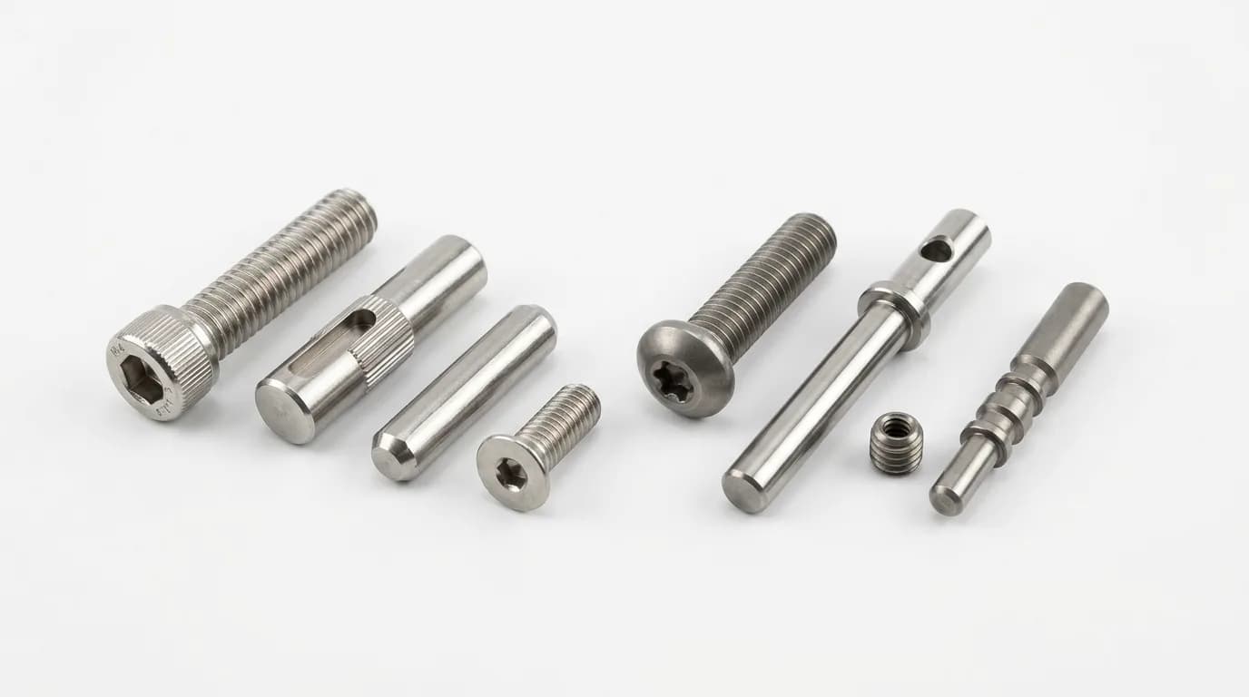
What Swiss-turned Parts Look Like
This is the kind of geometry Swiss turning is built for: small diameters, slender parts, and features that need to stay concentric in a single setup.

What Is Swiss Turning?
Swiss turning is a CNC lathe process where the bar stock slides through a guide bushing, keeping the cutting point supported within millimeters of the tool. A guide bushing is a precision collar, typically carbide or hardened steel, that grips the rotating bar right next to where the tool cuts. The headstock isn't fixed; it slides along the Z-axis, feeding the bar through the bushing. This is the opposite of conventional turning, where the headstock stays put and the tool travels.
Why It Exists: The Deflection Problem
On a conventional lathe, the bar stock extends from the chuck like a cantilever. The farther the tool cuts from the chuck, the more the bar deflects under cutting force. For a 0.125 in. (3.2 mm) diameter shaft that's 4 in. (100 mm) long, the L/D ratio is 32:1. At that ratio, even light cutting force causes measurable deflection, and the part tapers, chatters, or goes out of tolerance.
Swiss turning was invented in the 1870s for the Swiss watch industry, where watchmakers needed to turn tiny, slender pins and shafts that no fixed-headstock lathe could handle. The guide bushing solved the problem by ensuring the unsupported length never exceeds about 1 in. (25 mm), regardless of total part length.
Worked Example: Why L/D Matters
Part: A 0.250 in. (6.35 mm) OD shaft, 3 in. (76.2 mm) long
L/D ratio: 3.0 ÷ 0.250 = 12:1
On a conventional lathe: The unsupported length at the far end is the full 3 in. (76.2 mm). Deflection under a 10 lbf (44.5 N) side load on a steel bar:
δ ≈ 0.016 in. (0.41 mm), which is 16× a ±0.001 in. tolerance
On a Swiss lathe: The guide bushing limits unsupported length to ~0.5 in. (12.7 mm). Same calculation: δ ≈ 0.00009 in. (0.002 mm), well within tolerance.

How Swiss Turning Works vs CNC Turning
The core difference is where the workpiece is supported during cutting. In conventional turning, the bar is clamped in a fixed chuck and the tool moves along it, so the unsupported length grows with every inch of travel. In Swiss turning, the bar feeds through a stationary guide bushing while the headstock slides while in Swiss turning the tool stays in one place, and the unsupported length never changes.
Swiss-Type Lathe (Sliding Headstock)
Headstock
Bushing
Standard CNC Lathe (Fixed Headstock)
Chuck
Why This Matters for Your Part
If you send a 0.125 in. (3.2 mm) diameter shaft with an L/D of 20:1 to a conventional CNC lathe, the shop will either quote it with loose tolerances (±0.003 in. or wider), use a steady rest (adding setup time and cost), or turn it down. A Swiss lathe handles that part as routine work: tight tolerances, single setup, no special fixturing.
When to Choose Swiss Turning Over Conventional
The length-to-diameter (L/D) ratio is the single most important number for choosing between Swiss and conventional turning. L/D is calculated by dividing the part's total machined length by its smallest turned diameter. A 2 in. (50.8 mm) long shaft with a 0.25 in. (6.35 mm) OD has an L/D of 8:1. This ratio tells you how much the part will deflect under cutting force, and therefore which machine can hold your tolerances.

CNC Turning
Short, stocky parts. No deflection advantage from a guide bushing. Conventional lathe is more cost-effective with wider tool selection.
Crossover Zone
Swiss preferred if tolerances are below ±0.001 in. (±0.025 mm) or the part needs complex features (cross-holes, threads, flats) in one setup. Conventional works if tolerances are relaxed.
Swiss Turning
Conventional lathes cannot prevent deflection-induced taper without expensive fixturing. Swiss is the default process for high-L/D precision work.
Also Favor Swiss When:
- Part diameter is 1–32 mm (0.04–1.25 in.)
- Volume exceeds 200+ parts (amortizes higher machine rate)
- Multiple features needed in one setup (thread + cross-hole + flat)
- Concentricity between features is critical (<0.001 in. / <0.025 mm TIR)
- Surface finish requirement is below 16 µin. Ra (0.4 µm Ra)
Favor Standard CNC Turning When:
- Part diameter exceeds 32 mm (1.25 in.)
- L/D ratio is below 3:1 (no deflection problem)
- Tolerances are ±0.001 in. (±0.025 mm) or wider
- Low volume (1–50 parts) where setup cost dominates
- Large bore or internal turning (Swiss ID access is limited by bar OD)
Tolerance and Surface Finish: Swiss vs Conventional
Achievable tolerance is the tightest tolerance a process can reliably hold across a production run, not the lowest single part ever measured. The values below represent standard shop capabilities under normal conditions. Swiss turning's advantage comes from eliminating deflection: when the bar doesn't flex, the tool cuts where it's programmed, and the resulting dimension is more consistent.
| Feature | Swiss Turning | CNC Turning | Why the Difference |
|---|---|---|---|
| OD Tolerance | ±0.0002–0.0005 in. (±0.005–0.013 mm) | ±0.001–0.002 in. (±0.025–0.050 mm) | Guide bushing eliminates deflection-induced taper |
| ID Tolerance (bored) | ±0.0005–0.001 in. (±0.013–0.025 mm) | ±0.001–0.003 in. (±0.025–0.076 mm) | Bar stability reduces bore runout |
| Length Tolerance | ±0.001 in. (±0.025 mm) | ±0.002–0.005 in. (±0.050–0.127 mm) | Sliding headstock gives precise Z control |
| Concentricity (TIR) | 0.0003 in. (0.008 mm) | 0.001–0.002 in. (0.025–0.050 mm) | Single-setup machining eliminates re-chuck error |
| Surface Finish (Ra) | 8–16 µin. (0.2–0.4 µm) | 32–63 µin. (0.8–1.6 µm) | No chatter from deflection; consistent tool engagement |
Values represent typical production capabilities for parts with L/D ratios of 5:1–15:1. Actual results vary with material, tooling, and machine condition. Conventional turning achieves Swiss-like tolerances on short, stocky parts (L/D < 3:1).
Material Considerations for Swiss Turning
Swiss lathes use drawn bar stock, meaning round bars pulled through a die to achieve precise diameter and straightness, typically in 12 ft (3.6 m) lengths that feed automatically through the bar feeder. This means your material must be available as precision ground or centerless-ground bar in the required diameter. If it only comes as plate, billet, or castings, Swiss turning isn't an option.
| Material | Alloy / Grade | Swiss Suitability | Typical SFM | Notes |
|---|---|---|---|---|
| Free-machining brass | C360 | Excellent | 300–600 SFM (91–183 m/min) | Ideal Swiss material. Clean chip breaking, long tool life. |
| Free-machining steel | 12L14, 1215 | Excellent | 200–400 SFM (61–122 m/min) | Leaded steel for high-volume screw machine parts. |
| Stainless steel | 303, 304, 316L, 17-4 PH | Good | 100–250 SFM (30–76 m/min) | 303 preferred for machinability. 316L and 17-4 PH for medical/corrosion. |
| Aluminum | 6061-T6, 2011-T3 | Good | 500–1,000 SFM (152–305 m/min) | Long stringy chips need positive rake tooling and chip breakers. |
| Titanium | Ti-6Al-4V (ASTM F136 / ISO 5832-3) | Moderate | 50–120 SFM (15–37 m/min) | Low thermal conductivity. Requires high-pressure coolant. Tool wear is 3–5× faster than steel. |
| Engineering plastics | Acetal (Delrin), PEEK, nylon | Good | 300–800 SFM (91–244 m/min) | Guide bushing prevents plastic from flexing. Use uncoated carbide or PCD tooling. |
Bar Stock Constraint
Most Swiss machines accept bar stock from 1 mm (0.04 in.) to 32 mm (1.25 in.) in diameter. Some newer large-capacity Swiss lathes handle up to 38 mm (1.5 in.) or 51 mm (2 in.), but machine rates are higher. If your material isn't available as precision-ground or centerless-ground bar in the required diameter, you'll need conventional turning or a pre-grinding operation that adds cost and 1–2 weeks of lead time.
Not Sure If Your Part Needs Swiss Turning?
Upload your CAD file and our engineering team will review your geometry, L/D ratio, and tolerances to recommend the right process: Swiss turning, conventional CNC turning, or a combination. Every RFQ includes a free DFM review with process recommendations.
Upload Part for Free DFM ReviewCost Comparison: Swiss vs CNC Turning
Machine rate, the hourly cost to run the lathe, is not the same as part cost. Swiss lathes charge $125–250/hr compared to $75–150/hr for conventional turning. But machine rate only tells you half the story. What matters is cycle time × machine rate + setup cost, divided by the number of parts. Swiss lathes often win on per-part cost because they complete complex small parts in a single setup with shorter cycle times.
| Cost Factor | Swiss Turning | CNC Turning |
|---|---|---|
| Machine rate | $125–250/hr | $75–150/hr |
| Setup time (typical) | 2–4 hr | 1–2 hr (×2 if second op needed) |
| Cycle time (complex small part) | 30–90 sec | 2–5 min (including second-op handling) |
| Number of setups | 1 (live tooling + sub-spindle) | 1–2 (second op for back features) |
| Scrap rate (slender parts) | 1–2% | 5–15% (deflection, re-chuck error) |
Volume Break-Even: When Swiss Becomes Cheaper Per Part
Swiss turning has higher setup cost ($375–1,000 typical) than conventional ($75–300). But the shorter cycle time catches up quickly. Here's a worked example for a typical threaded stainless steel pin:
| Qty | Swiss $/part | Conventional $/part | Verdict |
|---|---|---|---|
| 50 | $18.50 | $12.00 | Conventional wins |
| 200 | $7.25 | $7.80 | Break-even zone |
| 500 | $4.90 | $6.50 | Swiss wins (25% savings) |
| 2,000 | $3.80 | $5.90 | Swiss wins (36% savings) |
| 10,000 | $3.40 | $5.60 | Swiss wins (39% savings) |
Example part: 303 stainless pin, 0.187 in. (4.75 mm) OD × 1.5 in. (38.1 mm) long, external thread + cross-hole + chamfer. Swiss: 45-sec cycle, $200/hr rate, $750 setup. Conventional: 3.5-min cycle (two setups), $100/hr rate, $250 setup.
DFM Rules for Swiss-Turned Parts
Design for manufacturing (DFM) means shaping your part geometry so the machine can produce it efficiently, with fewer setups, shorter cycle time, lower scrap. Swiss lathes have unique constraints compared to conventional turning: the guide bushing limits what you can do near the bar OD, live tooling positions are fixed, and back-working has reach limits. Following these rules avoids surprises at quoting.
Keep features accessible from the bar OD
Swiss tools approach from the bar circumference. Features that require internal access (deep bores relative to bar OD) may need a second operation.
Spec: Max bore depth: 3× bar diameter. Max bore diameter: 70% of bar OD.
Deep small-bore features require a separate drilling op, adding $2–5/part.
Design for single-setup completion
Swiss lathes have a sub-spindle that grabs the part after cutoff to machine the back face (back-working). Design back features within the sub-spindle's reach.
Spec: Back-working reach: typically 1.5–2× bar diameter from the cut-off face.
Features beyond sub-spindle reach require a manual second op, which adds 30–60 sec/part handling time.
Include thread relief grooves
Thread relief is a small undercut groove at the end of a threaded section that gives the threading tool a clean exit path, preventing a partial thread at the runout.
Spec: Min relief width: 1–2 thread pitches. Relief diameter: minor diameter minus 0.005 in. (0.13 mm).
Without relief, threads have ragged runout that may not pass a go/no-go gage.
Specify knurling on the OD before cutoff
Knurling (a crosshatch pattern pressed into the OD for grip) must be done while the bar is still supported by the guide bushing. After cutoff, the part is too short to re-fixture.
Spec: Knurl pitch: 21–33 TPI (teeth per inch) typical. Knurl depth: 0.010–0.025 in. (0.25–0.64 mm).
Knurling after cutoff requires custom fixturing, which adds $500–1,500 NRE.
Minimize cross-hole depth
Cross-holes are drilled by live tooling perpendicular to the bar axis. Deep cross-holes on small diameters risk drill breakage and are slow to peck-drill.
Spec: Max cross-hole depth: 2× drill diameter for through-holes, 1.5× for blind holes.
Exceeding depth limits increases cycle time 30–50% from peck-drilling and raises scrap from broken drills.
Allow a part-off witness mark
The part-off tool separates the finished part from the bar stock, leaving a small witness mark (nub or slight concavity) on the back face. Removing it requires a facing operation on the sub-spindle.
Spec: Typical witness mark: 0.005–0.015 in. (0.13–0.38 mm) high. If cosmetically critical, specify back-face facing.
Specifying "no witness mark" without allowing sub-spindle facing adds 5–15 sec/part cycle time.

Swiss Turning Applications: Medical Devices and Robotics
Swiss turning is the standard process for precision turned components in medical devices and robotics, two industries where small diameter, tight tolerances, and complex single-setup features are routine requirements.
Medical Device Components
Bone screws
Ti-6Al-4V (ASTM F136 / ISO 5832-3), 2.0–6.5 mm (0.08–0.26 in.) OD, self-tapping thread + hex socket. L/D 5:1–12:1. ±0.0005 in. (±0.013 mm) OD, 16 µin. Ra (0.4 µm) finish. Passivation per ASTM B600 (titanium) or citric acid per manufacturer protocol.
Catheter shafts and tips
316L stainless, 1.0–3.0 mm (0.04–0.12 in.) OD, L/D up to 30:1. Requires concentricity <0.0003 in. (0.008 mm) TIR and surface finish <8 µin. Ra (0.2 µm) for biocompatibility.
Dental implant abutments
Ti-6Al-4V or CoCrMo, 3.5–5.0 mm (0.14–0.20 in.) OD, internal thread + tapered interface. Tolerance ±0.0003 in. (±0.008 mm) on mating diameter.
Surgical instrument pins
17-4 PH stainless (H900 condition), 1.5–4.0 mm (0.06–0.16 in.) OD, cross-hole for spring clip. Single-setup completion critical for concentricity.
Robotics Components
Encoder shafts
303 stainless or 416 stainless, 3–8 mm (0.12–0.31 in.) OD, L/D 8:1–15:1. Requires ±0.0003 in. (±0.008 mm) OD tolerance and <0.0005 in. (0.013 mm) TIR runout for encoder wheel mounting.
Precision dowel pins
4140 alloy steel or 303 stainless, 2–6 mm (0.08–0.24 in.) OD, ground finish. ±0.0001 in. (±0.003 mm) on diameter for press-fit joint interfaces.
Electrical connector bodies
C360 brass, 3–10 mm (0.12–0.39 in.) OD, internal bore + external thread + knurl. All features completed in single setup for ≤0.0005 in. (0.013 mm) concentricity.
Miniature actuator shafts
17-4 PH stainless (H1025 condition), 4–12 mm (0.16–0.47 in.) OD, L/D 10:1–20:1. Keyway milled by live tooling. Tolerance ±0.0005 in. (±0.013 mm) on bearing journals.
Frequently Asked Questions
Related Resources
Ready to Quote Your Swiss-Turned Parts?
Upload your CAD file for a CNC turning quote. MakerStage can review the geometry, tolerances, and volume to route the quote toward Swiss turning or conventional CNC turning, with CMM inspection reports available on request. If you are preparing files now, use the RFQ checklist to include the details that speed up quoting.
Get CNC Turning Quote