ISO 2768 Tolerance Chart: How to Use It
ISO 2768-1:1989 supplies four general tolerance classes—f, m, c, and v—for covered linear and angular dimensions when a drawing explicitly invokes the standard. It does not apply automatically, and an individual tolerance beside a dimension takes precedence. This guide explains how to select the applicable table and range. It does not reproduce ISO’s normative tolerance values; obtain the controlling value from a licensed copy of the applicable edition.
By MakerStage Engineering Team · Published
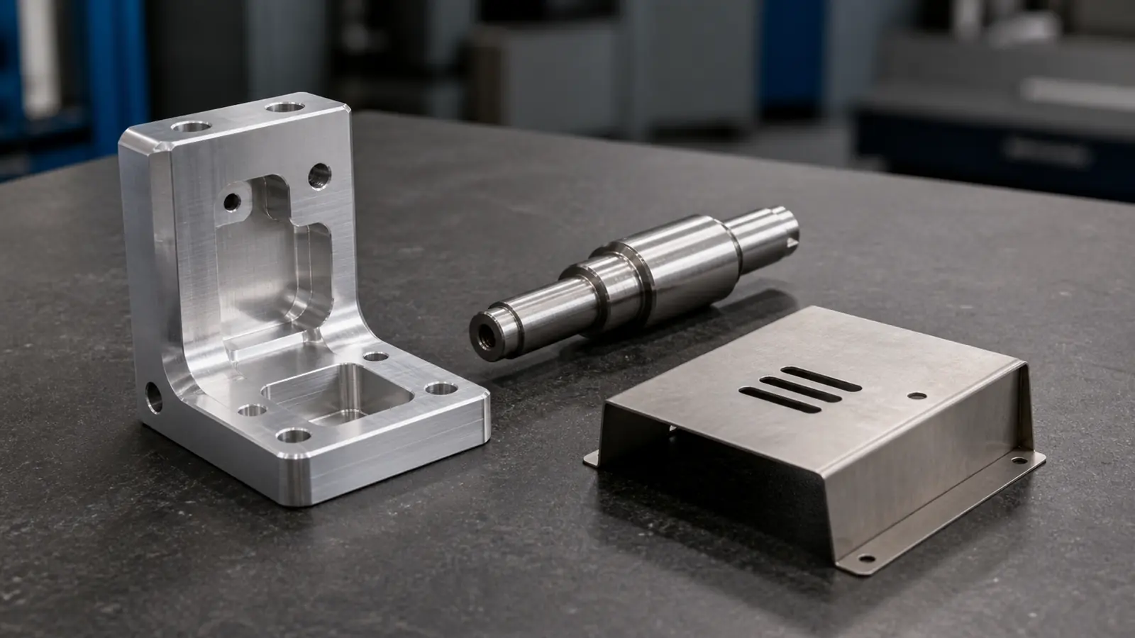
What ISO 2768-1 actually controls
A general tolerance is a drawing-level rule that fills in a tolerance only for covered dimensions without their own tolerance.
A tolerance defines the acceptable variation around a nominal value. ISO 2768-1 simplifies drawings by letting one class cover specified kinds of dimensions that do not already have an individual tolerance. For broader machining capability and cost context, use the CNC tolerance selection guide.
The standard’s stated primary scope is parts produced by metal removal or formed from sheet metal. Confirm suitability before applying it to castings, molded plastics, weldments, 3D printed parts, or other processes.
Two terms to know before checking scope
- Nominal dimension
- The intended value printed on the drawing. Use this value—not the measured result—to choose a table range.
- General vs individual tolerance
- A general tolerance fills a covered gap. An individual tolerance is written beside one dimension or characteristic and takes precedence only for that dimension or characteristic.
Hypothetical drawing example: if the title block invokes ISO 2768-1 class m but a shaft is marked Ø12.00 ±0.02 mm, the written ±0.02 mm governs that shaft diameter. Do not add a general ISO tolerance to it.
Covered when untoleranced
- Linear sizes, diameters, steps, radii, and distances
- External radii and chamfer heights on broken edges
- Angular dimensions, including right angles not governed by a referenced general geometrical-tolerance standard
- Dimensions created by machining assembled parts
Not governed by Part 1
- Dimensions with their own individual tolerances
- Dimensions covered by another referenced standard
- Bracketed reference or auxiliary dimensions shown for information rather than inspection acceptance
- Boxed theoretically exact dimensions whose allowed variation comes from a separate geometrical control
Scope source: official ISO 2768-1 scope preview.
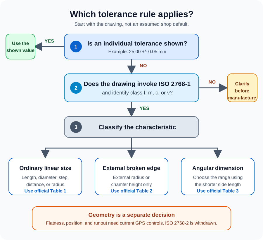
Which tolerance rule applies?
- 1Check the dimensionIf an individual tolerance is shown, use it for that characteristic.
- 2Check the drawing noteIf ISO 2768-1 and a class are not invoked, stop and clarify.
- 3Classify the characteristicChoose the official linear, broken-edge, or angular table. For an angular dimension, select the range using the nominal length of the shorter side—not the angle value or a measured length.
Unindicated right angle? First check whether a referenced geometrical-tolerance requirement governs, such as a legacy ISO 2768-mK callout on an existing drawing. If it does, follow that requirement; otherwise use Part 1 Table 3.
f, m, c, and v describe the selected tolerance class
The drawing's class letter selects a column in the official table. It is not a quality grade, fit designation, or promise that every supplier can hold that tolerance.
Fine
For ordinary linear dimensions, f is the tightest tabulated class where a value exists. For angular dimensions and broken edges, f and m use identical values.
Medium
A commonly encountered class, but not an automatic ISO default for CNC machining or every supplier.
Coarse
A wider general band for features whose function permits more variation. Critical fits still need explicit control.
Very coarse
For ordinary linear and angular dimensions, v is generally the widest tabulated class where a value exists. In the broken-edge table, c and v use identical values. Separately, some ordinary-linear class/range combinations have no tabulated value.
Use six checks before applying an ISO 2768-1 value
Start with the drawing—not the table. These checks prevent you from using the right number for the wrong feature or document.
Read the controlling note
Invoked means explicitly named. Confirm that the title block, drawing note, specification, or contract names ISO 2768-1, the applicable edition, and class f, m, c, or v.
Check precedence and exclusions
Check the dimension itself before using the general class. A written individual tolerance or another referenced standard wins. Reference or auxiliary dimensions are informational. Boxed theoretically exact dimensions receive their allowed variation from separate geometrical controls. Neither receives a Part 1 general tolerance.
Classify the characteristic
Choose ordinary linear, external radius or chamfer height for a broken edge, or angular. Each category uses a different official table.
Select with the nominal metric value
Nominal means the value printed on the drawing. If the drawing says 42.0 mm and inspection reads 41.92 mm, use 42.0 mm to choose the range. The measured value is used later for acceptance.
Consult the licensed table
The normative table is the official table whose values control the drawing. In a licensed copy of the applicable edition, read the intersection of the feature type, nominal range, and class. Never invent a value for a dash.
Calculate and inspect
Bilateral means the same permitted deviation applies above and below nominal. Calculate both limits, use a suitable measuring tool, and apply the agreed pass/fail rule near a limit.
Quick cheat sheet: which lookup path should I use?
Match the characteristic to its controlling nominal input, then use the invoked class in the applicable official table.
Ordinary linear dimension
- Use
- Nominal size shown on the drawing
- Look up
- Linear-dimension table and invoked class
- Stop and clarify
- An individual tolerance or another standard governs, or the table supplies no value.
External broken edge
- Use
- Nominal external radius or chamfer height
- Look up
- Broken-edge table and invoked class
- Stop and clarify
- The feature is an internal fillet, another radius type, or outside the table scope.
Angular dimension
- Use
- Nominal length of the shorter side
- Look up
- Angular table and invoked class
- Stop and clarify
- The angle magnitude or a measured length was used, or a separate geometrical requirement governs.
Convert the selected deviation into limits
Let N be the nominal dimension and T the symmetric deviation selected from the applicable table. The lower and upper limits are the smallest and largest acceptable values. The total tolerance is the full span between them, so a symmetric ±T deviation creates a span of 2T.
Hypothetical math—not an ISO table value: if N = 40.00 mm and the applicable table supplies T = 0.03 mm, the limits are 39.97 mm and 40.03 mm. The total tolerance is 0.06 mm. The actual T must come from the controlling drawing or a licensed copy of the applicable edition.
Use the standard’s millimetre values to select ranges. If the drawing or inspection record uses inches, convert using 1 in = 25.4 mm exactly and round only to the documented resolution.
From nominal to limits
For a symmetric ±T tolerance, the permitted values extend equally below and above nominal N.
- Lower limit
- N − T
- Nominal
- N
- Upper limit
- N + T
Total specification span = 2T
N comes from the drawing. T comes from the governing requirement. Obtain the actual T from the controlling drawing or licensed standard; no ISO table value is shown here.
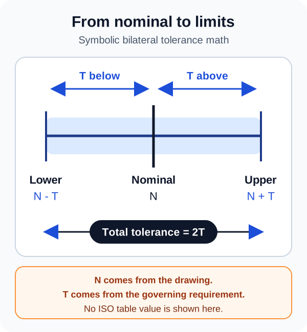
This diagram defines the specification limits only. When a measurement is near either limit, the acceptance decision must also follow the agreed conformity decision rule and account for measurement uncertainty.
A breakpoint stays in its ending range
If the official row is written as “over A up to B,” a nominal value exactly equal to B remains in that row. Only a value above B moves forward.
Metric values control range selection
The standard uses millimetre values to select its ranges. Never select an interval from a rounded display conversion.
A dash or missing range means stop
If the selected cell has a dash, supplies no value, or the nominal size is outside the published range, specify the tolerance individually or obtain clarification. Never treat the gap as zero or extrapolate a value.
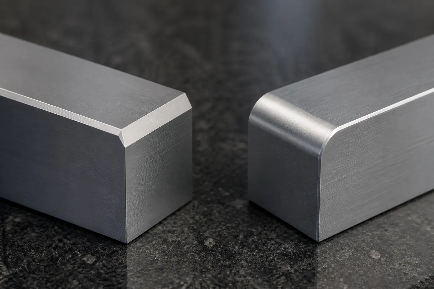
External radii and chamfer heights use a separate category
This category exists because a broken edge is specified differently from an ordinary size. Do not apply it to internal fillets or every radius on the part.
A chamfer is a flat bevel across an outside corner. An external radius is a convex rounded outside corner. An internal fillet is the concave rounded corner inside a pocket or between two surfaces.
Select with the dimension shown on the drawing. Use the nominal metric radius or chamfer height—not a measured edge or rounded inch conversion—to select the interval in the applicable table.
Angular ranges use the shorter side length
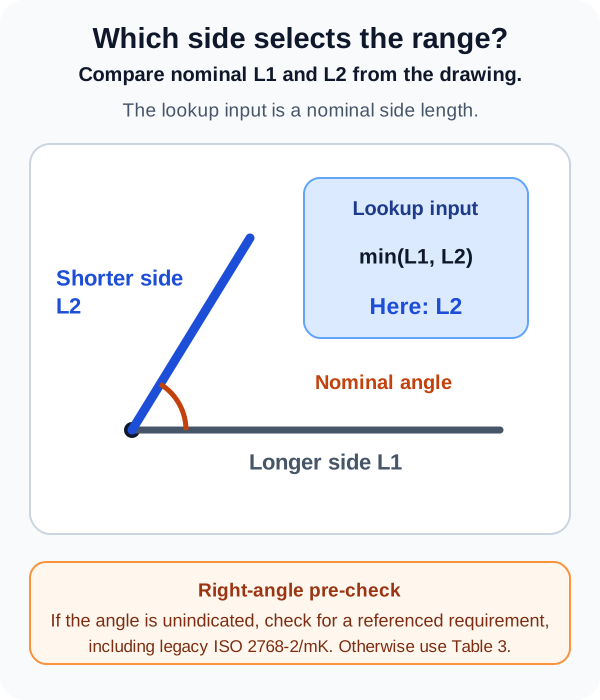
First confirm that no referenced geometrical-tolerance requirement governs. Then use the nominal length of the shorter side that forms the angle to select the ISO 2768-1 Table 3 range—not the angle value or a measured side length.
Which side sets the range?
Compare nominal side lengths L1 and L2 from the drawing.
Choose the shorter nominal side
Lshort = min(L1, L2)
Here: L2 is shorter, so use L2.
Unindicated right angle? Check whether a referenced geometrical-tolerance requirement governs, including a legacy ISO 2768-mK callout. Otherwise use the nominal shorter-side length with Part 1 Table 3. Never use the angle value or a measured side length to select the range.
Calculate angular limits symbolically
Hypothetical example: for nominal sides of 40 mm and 70 mm, select the angular interval using 40 mm. Then obtain α from the invoked class and apply it above and below the nominal angle.
State the edition and class in the title block
A supplier cannot infer a class from the absence of individual tolerances. Make the governing note explicit and keep critical requirements beside their dimensions.
The title block is the drawing panel that usually identifies the part, revision, units, material, and general notes. It is where a drawing-level ISO 2768 requirement is commonly stated.
Clear title-block note
GENERAL DIMENSIONAL TOLERANCES: ISO 2768-1:1989, CLASS m.The shorter designation ISO 2768-m appears on many drawings. Including the part, edition, and class makes the governing requirement unambiguous. The engineering drawing interpretation guide explains how title blocks, notes, dimensions, and revisions work together.
Drawing-release checklist
- 1Identify the units, drawing revision, ISO part and edition, and selected class.
- 2Place individual tolerances on features that control assembly or function—for example, a pin-and-hole fit, two mating surfaces, or a dimension whose variation adds to an assembly stack.
- 3Specify geometrical controls where form, orientation, or location matters. A datum is a theoretically exact reference—such as a plane, axis, or point—established from a datum feature on the part and used to locate or orient another feature.
- 4State surface finish, thread class, burr or edge condition, and inspection needs separately; ISO 2768-1 does not supply them.
- 5Ask the supplier to confirm that both the manufacturing process and the inspection method can hold and verify the required tolerance.
Before requesting a quote, add the title-block note, critical individual tolerances, and inspection requirements using the RFQ drawing checklist. MakerStage’s CNC milling and turning overview explains the supported processes and free design-for- manufacturability feedback.
Inspect the requirement that actually governs
Inspection starts with the drawing requirement, not the number on the measuring tool. First identify the applicable limits; then compare the measured result using a suitable method.
Inspection sequence: limits, measure, decide
Keep these three jobs separate so a display reading is never mistaken for the complete acceptance decision.
- 1Obtain the limits from the individual tolerance or the applicable ISO 2768-1 lookup; inspect geometrical requirements separately.
- 2Choose a measurement method and resolution suitable for the characteristic and tolerance.
- 3Apply the agreed conformity decision rule and account for measurement uncertainty near a limit.

A result can sit just inside a limit while its stated measurement-uncertainty interval crosses that limit. Apply and document the agreed conformity decision rule. The dimensional inspection methods guide compares practical inspection options and documentation.
If the agreed conformity decision rule determines that a result is nonconforming, record the nonconformance. A supplier or inspector cannot self-waive it; acceptance needs a documented concession from the authority designated by the drawing, contract, or quality procedure.
mK is a legacy combined callout
In ISO 2768-mK, m refers to Part 1 dimensional tolerances and K referred to a geometrical class in ISO 2768-2:1989. That second part is withdrawn.
- Published dimensional edition
- ISO 2768-1:1989
- ISO lists this as the published Part 1 edition. Use the edition named by the drawing or contract.
- Part 1 record
- Under publication
- ISO 2768 Edition 2
- Will replace ISO 2768-1:1989. Confirm the required edition before releasing a new drawing.
- Edition 2 record
- Withdrawn legacy standard
- ISO 2768-2:1989
- Withdrawn 4 February 2021. H, K, and L may still govern an existing drawing or contract but are not current guidance for new work.
- Part 2 record
- Successor standard
- ISO 22081:2021
- Gives rules for defining and interpreting general geometrical specifications and general size specifications. It is not an automatic one-to-one replacement for class K.
- ISO 22081 record
A withdrawn standard can still appear in a contract or legacy drawing. Do not simply replace an old ISO 2768-mK note with ISO 22081 and assume the acceptance meaning stays the same. The drawing owner must confirm which revision governs, define the required geometrical controls, and approve the clarification before manufacture.
Size describes how large a feature is, while geometry describes its form, orientation, or location. A hole can have the correct diameter and still be in the wrong position. Part 1 does not by itself control flatness, straightness, position, coaxiality, or runout. Use the geometric tolerancing fundamentals to separate size from form, orientation, and location.
Frequently Asked Questions
What is ISO 2768?
What does ISO 2768-m mean on a drawing?
What does ISO 2768-mK mean?
What is the difference between ISO 2768 classes f, m, c, and v?
Is ISO 2768-2 still valid?
How do I find the ISO 2768 tolerance for a dimension?
Does ISO 2768 override a tolerance shown next to a dimension?
What is the difference between ISO 2768 and ISO 286?
Can an out-of-tolerance part still be accepted?
Related Resources
Put the governing tolerances in the RFQ package
Include the drawing revision, ISO edition, selected class, individually toleranced critical features, and inspection requirements. MakerStage provides free DFM feedback with CNC machining RFQs.
Upload Your Drawing for a CNC Quote