Customer-designed component guide
Cold Plate Manufacturing Considerations
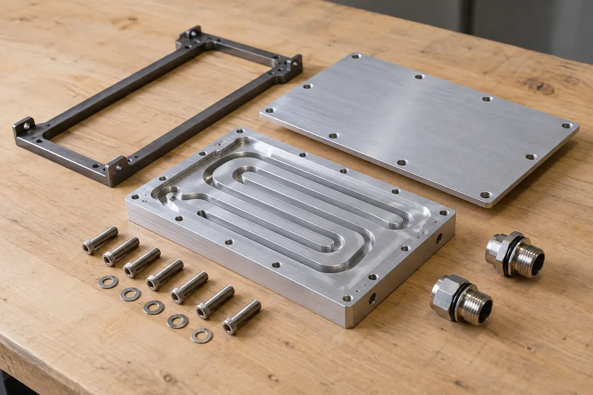
Cold plate manufacturing needs defined channels, interfaces, materials, assembly boundaries, inspection, and test scope for customer-designed parts.
How to use this guide
Use it with the liquid cooling component manufacturing page, review the relevant CNC machining capability, then prepare the controlled files and acceptance criteria before submitting an RFQ.
Define the manufactured component boundary
A cold plate may combine machined plates, covers, seals, fittings, joining, and tests that require different suppliers and controls.
Start the RFQ with a scope diagram that marks which customer-designed parts are machined, which purchased items are supplied, and who owns cleaning, assembly, joining, and testing.
MakerStage can review customer-designed machined components for manufacturability. This page does not imply brazing, bonded assembly, leak testing, flow testing, or thermal validation.
- Machined base or channel plate
- Cover and mounting components
- Customer-selected fittings and seals
- OEM- or qualified-provider-owned joining, cleaning, assembly, and testing
Control channels and functional interfaces
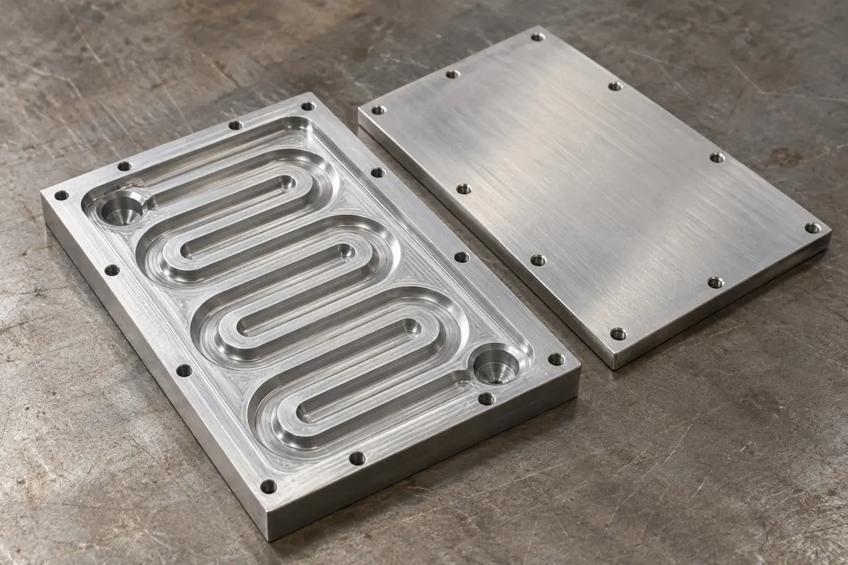
Channel geometry must be manufacturable while preserving the OEM’s fluid and thermal design intent.
Dimension channel width, depth, corner radii, transitions, inlet and outlet features, cover interface, sealing land, mounting datums, and keep-out zones. Identify any surface where tool marks or finish are functionally limited.
The OEM owns channel architecture, pressure drop, flow distribution, thermal resistance, device interface, and material compatibility. Manufacturing feedback should be returned as proposed changes for customer approval.
- Channel and transition geometry
- Port and seal interfaces
- Device-contact and mounting datums
- Surface finish and keep-out requirements
| Feature | Customer-controlled input |
|---|---|
| Fluid path | Channel architecture and performance requirement |
| Cover interface | Seal or joining design and surface requirement |
| Device interface | Flatness, finish, load, and keep-out definitions |
Specify every secondary process
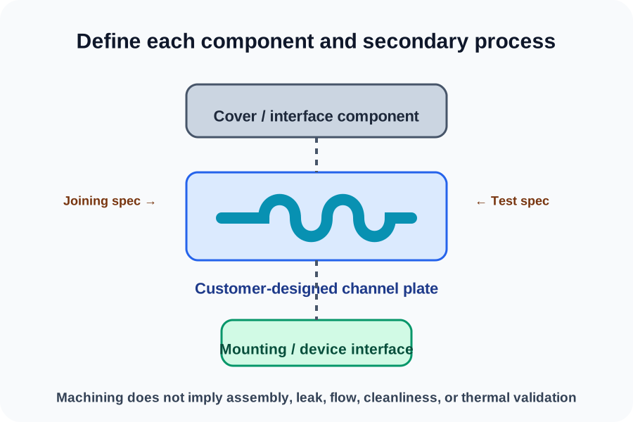
The machined shape alone does not define a finished cold plate.
Call out material condition, deburring, finish, masking, cleaning, closure hardware, seal installation, joining method, and packaging as separate requirements.
If the OEM uses a joined assembly, it should supply the approved process specification, joint design, qualification requirements, inspection method, and responsible test procedure to the qualified provider.
- Material grade and condition
- Deburring, finish, and masking
- Joining or sealing specification
- Cleanliness and protective packaging
Tie verification to written acceptance criteria
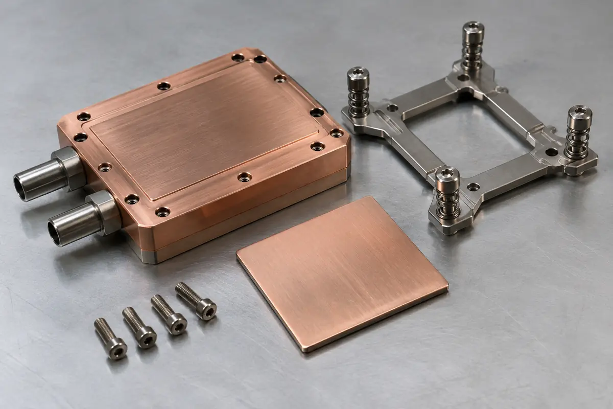
Dimensions, leak integrity, flow, cleanliness, and thermal performance require different evidence.
Request dimensional or CMM records for critical geometry when needed. Define material records and traceability in the RFQ.
Any pressure, leak, flow, cleanliness, or thermal test needs a separate procedure with method, equipment or fixture ownership, limits, sample plan, and report expectations.
- Critical-feature dimensional report
- CMM report when appropriate
- Material test report on request
- Separately defined functional tests and customer approval
MakerStage focuses on customer-designed machinable components
- Machined plates, housings, frames, and related customer-designed parts
- Free DFM review with the RFQ
- Dimensional, CMM, and material records on request
- No implied brazing, bonded assembly, leak, flow, cleanliness, pressure, or thermal validation
Technical references
These primary references provide system context. Project requirements still belong in the customer-controlled drawing and specification.
Frequently Asked Questions
Does MakerStage design the thermal path?
Are joining and leak testing included with machined plates?
Which files help a cold plate component RFQ?
Bring a controlled component package
Upload the model, drawing, quantity, revision, and requested records. MakerStage will review manufacturability against the supplied scope.
Start an RFQ