Customer-designed component manufacturing
Liquid Cooling Machined Components
Liquid cooling machined components need clear interfaces, materials, cleanliness, and inspection scope. Prepare customer-designed parts for RFQ.
How to use this guide
Use it with the liquid cooling component manufacturing page, review the relevant CNC machining capability, then prepare the controlled files and acceptance criteria before submitting an RFQ.
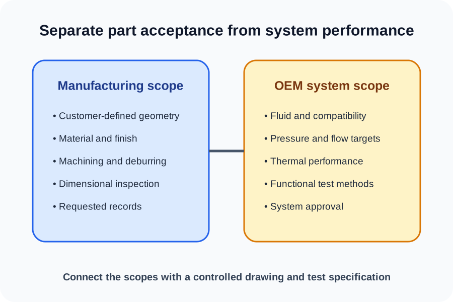
Separate the components from the cooling system
Machined hardware can be quoted from customer-controlled geometry without making a system-performance claim.
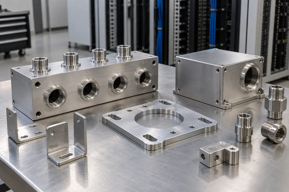
Relevant component families include manifold blocks, channel plates, cover plates, housings, mounting frames, interface brackets, and test fixtures built to supplied designs.
The OEM defines fluid, pressure, temperature, flow, sealing, compatibility, and performance requirements. Those inputs guide the part specification; they are not inferred by the manufacturer.
- Manifold blocks and distribution plates
- Customer-designed channel or cover plates
- Housings, mounting frames, and brackets
- Fixtures and non-production support hardware
Control geometry, material, and interfaces
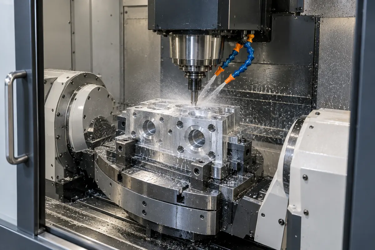
Fluid-facing parts need the same disciplined drawing controls as other precision components, plus clearly specified interfaces.
Provide material grade and temper, port and thread definitions, sealing surfaces, surface-finish requirements where functional, datums, tolerances, edge conditions, and any restricted tool marks.
If internal passages or intersecting features are used, show how they connect and identify plugs, caps, or secondary closures as customer-controlled design elements.
- Material and condition
- Port, thread, and sealing interface definitions
- Datum and tolerance scheme
- Surface finish and edge requirements
| Drawing input | Supplier question it answers |
|---|---|
| Port specification | Which tool and gauge control the interface |
| Sealing surface | Which area needs finish and flatness control |
| Passage map | How intersecting features connect |
Specify post-machining scope explicitly
Cleaning, deburring, coating, assembly, and testing are separate operations with separate acceptance criteria.
State the required deburring and cleanliness condition in objective terms. If coating, passivation, conversion coating, or masking is required, identify the approved finish and protected interfaces.
Do not assume pressure, leak, flow, cleanliness, or thermal testing is included. The OEM or a separately qualified provider should define and execute the method, medium, limits, sample plan, fixture responsibility, acceptance rule, and required record.
- Deburring and edge condition
- Approved finish and masking
- Customer-defined cleanliness requirement
- Separately specified test method and acceptance limit
Plan inspection around functional interfaces
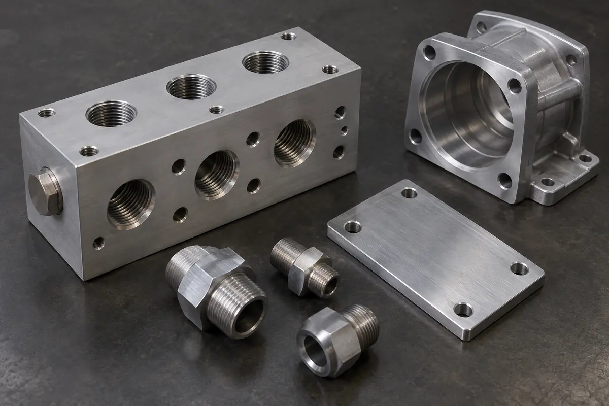
Inspection should verify the features the customer has tied to fit or function.
Identify critical port locations, sealing surfaces, mounting datums, and mating faces. Request a dimensional report or CMM report when those records are needed for acceptance.
Material test reports can be requested for material traceability. System-level validation and functional testing remain the customer’s responsibility or must be handled by a separately qualified provider.
- Critical port and mounting locations
- Sealing-surface geometry
- Dimensional or CMM report on request
- Material test report on request
Manufacturing scope remains component-specific
- CNC machining of customer-designed parts
- 3-axis, 5-axis, turning, and Swiss processes as geometry requires
- Inspection reports, CMM reports, and MTRs on request
- No implied thermal, pressure, leak, flow, cleanliness, or system validation
Technical references
These primary references provide system context. Project requirements still belong in the customer-controlled drawing and specification.
Frequently Asked Questions
Can MakerStage manufacture a complete cold plate?
What should a fluid-component drawing include?
Can I request CMM and material records?
Bring a controlled component package
Upload the model, drawing, quantity, revision, and requested records. MakerStage will review manufacturability against the supplied scope.
Start an RFQ