Mechanical design guide
Rackmount Chassis Design and Enclosure DFM
Rackmount chassis DFM reviews formed-part fit, service access, hardware placement, and the inputs needed for a clearer manufacturing RFQ.
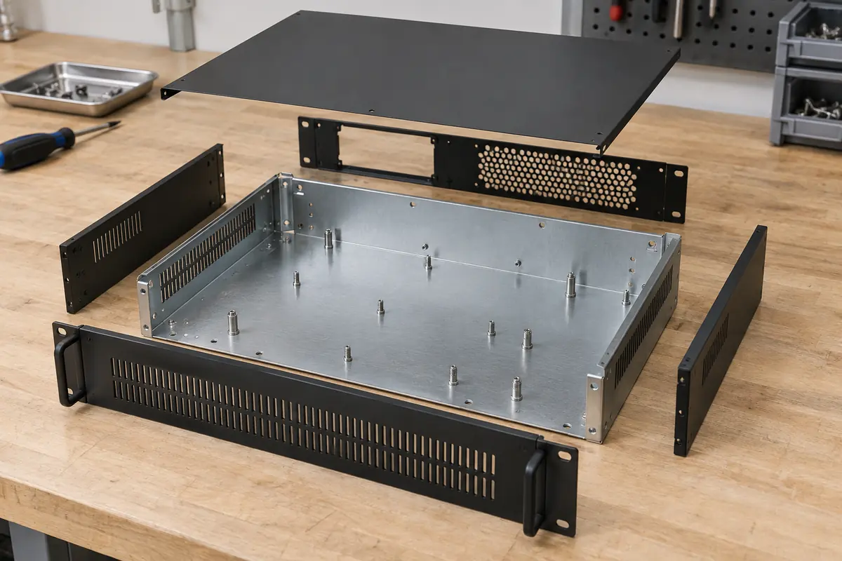
How to use this guide
Use it with the data center sheet metal manufacturing page, review the relevant sheet metal capability, then prepare the controlled files and acceptance criteria before submitting an RFQ.
Treat the chassis as an interface stack
Rack attachment, modules, connectors, airflow paths, and service clearances all compete for the same envelope.
Begin with the customer-selected rack standard and the actual mating geometry. Mark rail, flange, handle, connector, and removable-panel interfaces in the controlled assembly.
A nominal rack-unit description is not a substitute for a dimensioned interface drawing. The OEM remains responsible for standard selection and system compatibility.
- Rack and rail attachment points
- Module and PCB mounting interfaces
- Connector and cable clearances
- Fan, filter, and service envelopes
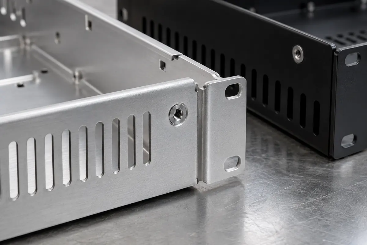
Dimension what must fit after forming
Bend sequence and tolerance stack influence the final enclosure more than isolated flat dimensions.
Use finished datums for flange location, opening position, and panel-to-panel alignment. Place reliefs and seams where they support the intended bend sequence and assembly access.
State whether critical features are inspected before or after hardware insertion, welding, coating, or secondary machining.
- Finished flange-to-flange dimensions
- Bend relief and corner treatment
- Hole-to-bend and hardware clearances
- Datum strategy for mating panels
| Decision | Control on the drawing |
|---|---|
| Panel fit | Finished datums and gap targets |
| Captive hardware | Part number, side, and installation state |
| Service access | Removal direction and keep-out envelope |
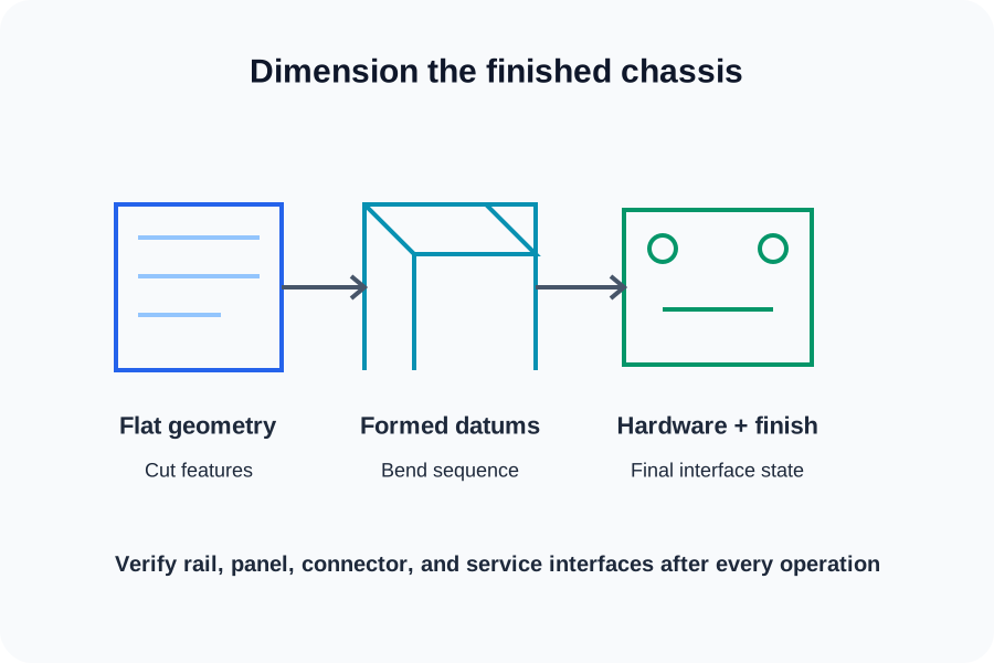
Release one controlled package
Quote accuracy improves when every supplier sees the same model, drawing, BOM notes, and revision.
Include a STEP assembly, individual part files, controlled drawings, and a simple scope matrix that separates fabricated parts from purchased hardware.
For prototype builds, identify which interfaces are learning objectives. For later builds, freeze acceptance criteria and document any approved deviations through revision control.
- Assembly model and individual part models
- Controlled drawings with revision identifiers
- Purchased-hardware list and installation notes
- Prototype learning goals and production acceptance criteria
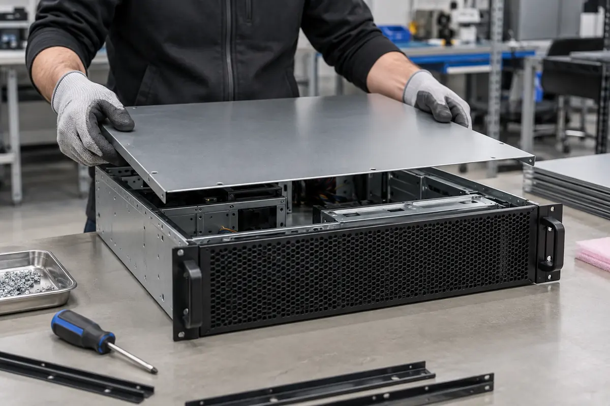
Define verification without implying certification
Part inspection and system qualification answer different questions.
A dimensional report can verify specified features on a fabricated part. It does not prove rack compatibility, airflow, EMI performance, structural capacity, ingress protection, or regulatory compliance.
If external testing is required, identify the test owner, standard, fixture, sample size, acceptance limit, and report format before supplier selection.
- Part-level dimensional inspection
- Customer-owned assembly fit validation
- Customer-defined system testing
- Separate scope for third-party certification
A chassis DFM review focuses on manufacturability
- Finished part geometry and bend sequencing
- Hardware access and inspection datums
- Customer-defined rack and assembly interfaces
- No implied rack, airflow, EMI, environmental, or safety certification
Technical references
These primary references provide system context. Project requirements still belong in the customer-controlled drawing and specification.
Frequently Asked Questions
Does a 19-inch rack description fully define a chassis interface?
What should be inspected on a rackmount enclosure?
Can MakerStage validate airflow or EMI performance?
Bring a controlled component package
Upload the model, drawing, quantity, revision, and requested records. MakerStage will review manufacturability against the supplied scope.
Start an RFQ