Drawing and RFQ checklist
Liquid Cooling Manifold Manufacturing Checklist
Liquid cooling manifold manufacturing starts with controlled ports, passages, sealing interfaces, materials, inspection, and defined test scope.
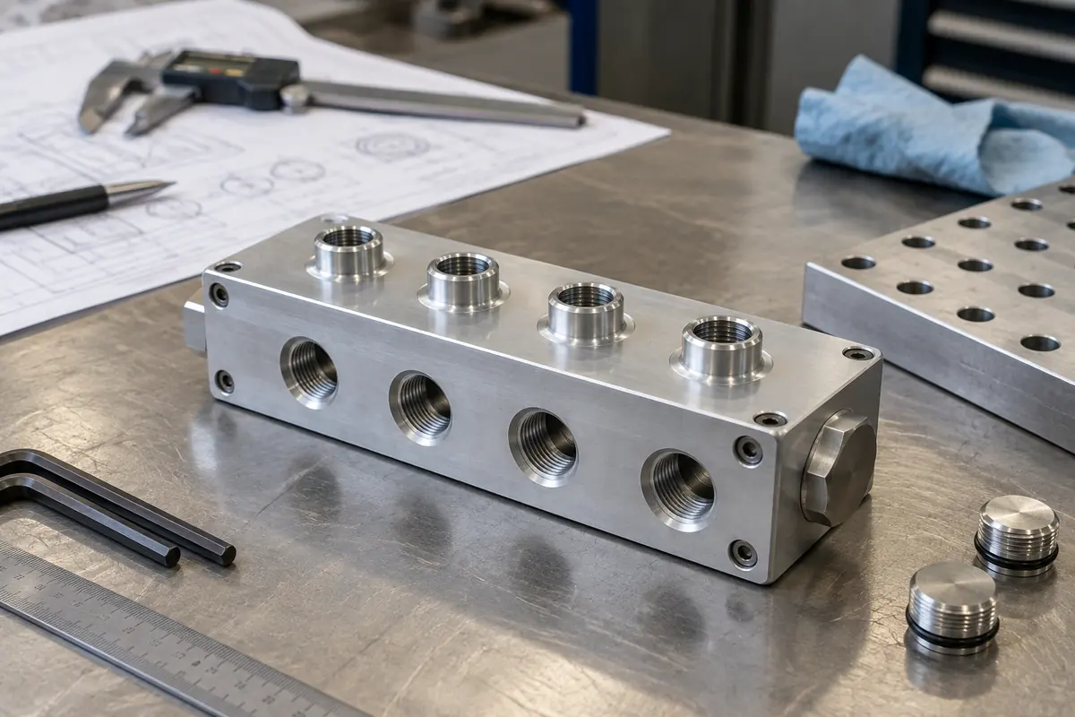
How to use this guide
Use it with the liquid cooling component manufacturing page, review the relevant CNC machining capability, then prepare the controlled files and acceptance criteria before submitting an RFQ.
Freeze the manifold architecture first
The customer controls the fluid circuit, connection scheme, service strategy, and rack interfaces.
Provide a controlled passage map that identifies every inlet, outlet, branch, cross-drill, plug, drain, vent, sensor feature, and mounting interface.
Reference the OEM-selected rack or cooling architecture where useful, but place the actual project requirements on the released drawing and specification.
- Inlet, outlet, and branch mapping
- Cross-drill and closure strategy
- Drain, vent, and sensor provisions
- Mounting and service interfaces
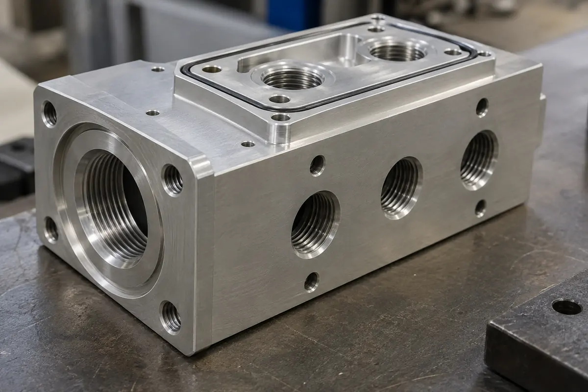
Fully define ports and sealing interfaces
A nominal thread name rarely defines the complete functional interface.
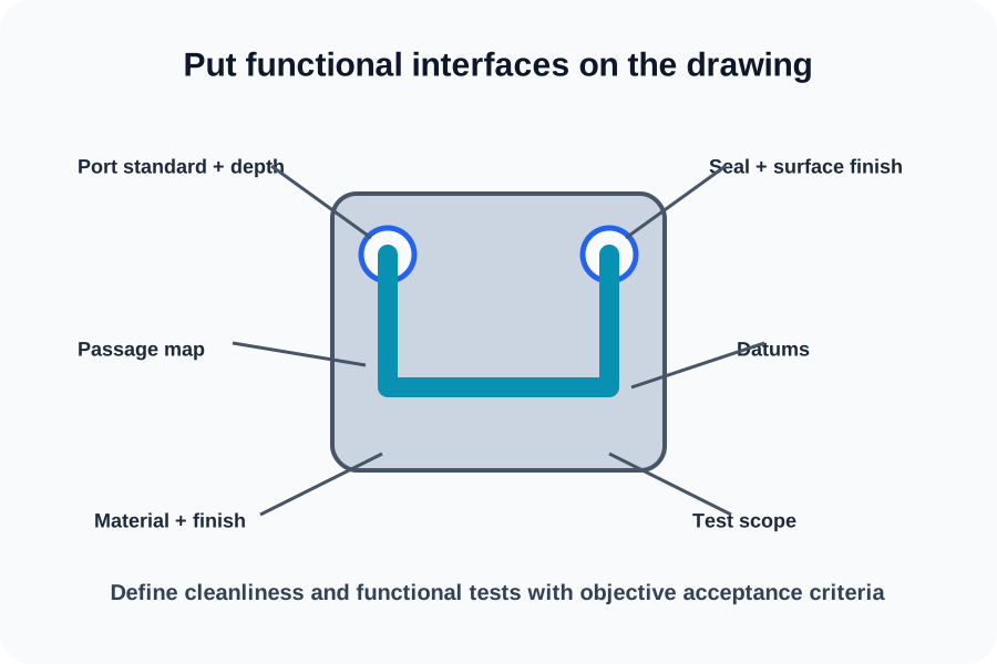
Specify thread standard and class, depth, lead-in, spotface, sealing method, groove geometry, surface finish, and any clocking or orientation requirement.
Identify the exact datum scheme used to locate ports relative to mounting and mating features. Do not make the supplier infer seal compression or connector engagement.
- Thread form, class, and engagement depth
- Seal type and groove definition
- Mating-face finish and geometry
- Port location and orientation datums
| Interface | Required control |
|---|---|
| Threaded port | Standard, class, depth, spotface, and gauge |
| Seal groove | Geometry, finish, and datum relationship |
| Mounting face | Flatness or profile only when function requires it |
Review access, deburring, and closures
Long passages and intersecting bores create tool-access and debris-removal questions.
Discuss tool reach, drill wander risk, burr access, plug installation, and inspection access during DFM. Critical intersections should be visible in section views or a passage table.
State material, finish, masking, and objective cleanliness requirements. If a process is mandatory, identify it rather than relying on a generic clean-part note.
- Tool access and passage depth
- Deburring at intersections
- Closure hardware and installation scope
- Finish, masking, and cleanliness criteria

Separate dimensional acceptance from functional tests
Dimensional inspection verifies drawing features; functional testing needs its own procedure.
Request inspection records for critical port, face, and mounting geometry as needed. Specify gauges or methods when the standard requires them.
Pressure, proof, leak, flow, burst, cleanliness, and thermal tests are not implied. Define each requested test with medium, limits, duration, temperature, sample plan, fixture responsibility, and report format.
- Critical-feature inspection plan
- Thread or port gauge requirements
- Separately defined functional-test procedure
- Customer approval of deviations and results
The checklist supports a customer-owned design
- MakerStage reviews the supplied manifold for manufacturability
- The OEM owns fluid architecture and functional requirements
- Dimensional reports and material records are available on request
- Pressure, leak, flow, cleanliness, and thermal tests require separate scope
Technical references
These primary references provide system context. Project requirements still belong in the customer-controlled drawing and specification.
Frequently Asked Questions
What is the minimum manifold RFQ package?
Is leak testing automatically included?
Why include a passage map?
Bring a controlled component package
Upload the model, drawing, quantity, revision, and requested records. MakerStage will review manufacturability against the supplied scope.
Start an RFQ