Customer-designed copper component guide
Busbar Manufacturing Considerations
Busbar manufacturing needs defined copper grade, formed geometry, holes, contact areas, finishes, insulation, and inspection scope.
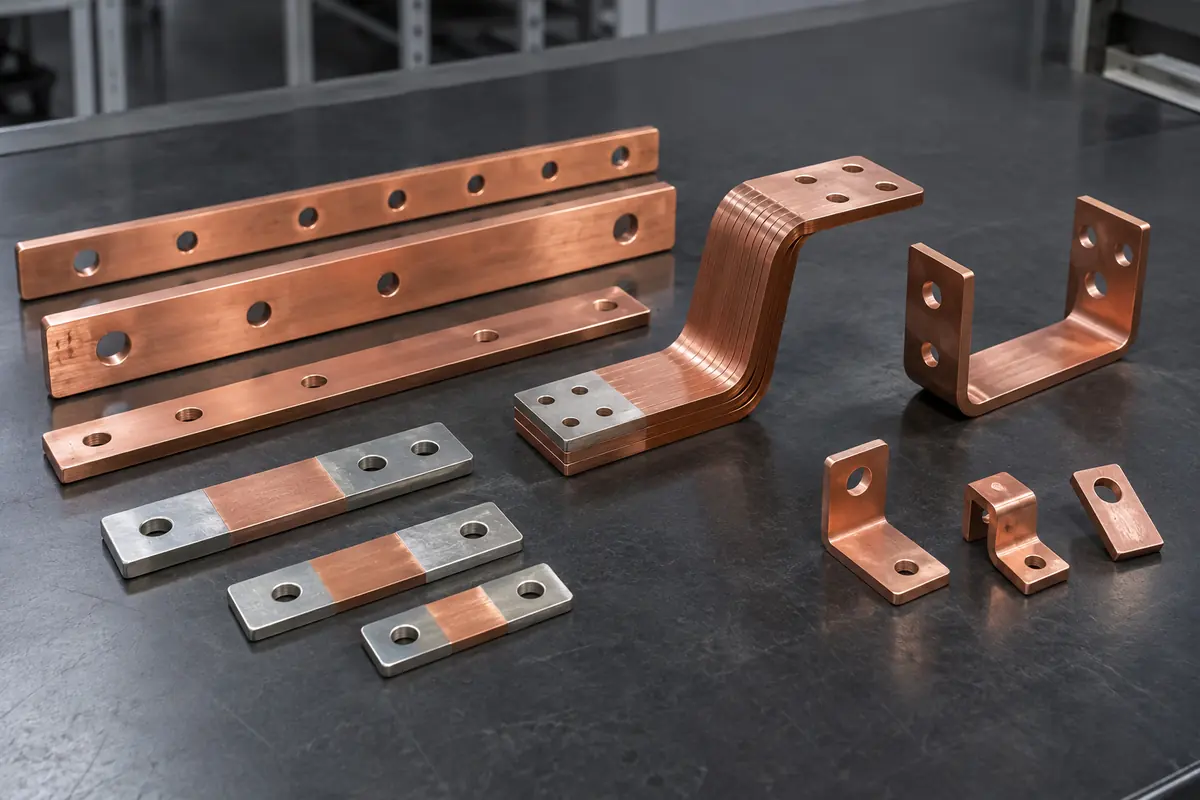
How to use this guide
Use it with the custom busbar component manufacturing page, review the relevant sheet metal capability, then prepare the controlled files and acceptance criteria before submitting an RFQ.
Translate electrical intent into controlled part requirements
The OEM defines current, voltage, temperature rise, clearances, creepage, fault conditions, and system architecture.
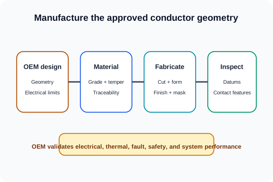
The manufacturing drawing should translate the approved electrical design into material, cross-section, routing, interfaces, geometry, and acceptance requirements.
Do not ask the fabricator to infer ampacity or electrical suitability from shape. Provide the customer-approved geometry and identify any feature that cannot change during DFM.
- Customer-approved conductor geometry
- Copper grade and temper
- Mounting and connection interfaces
- OEM-owned electrical and thermal limits
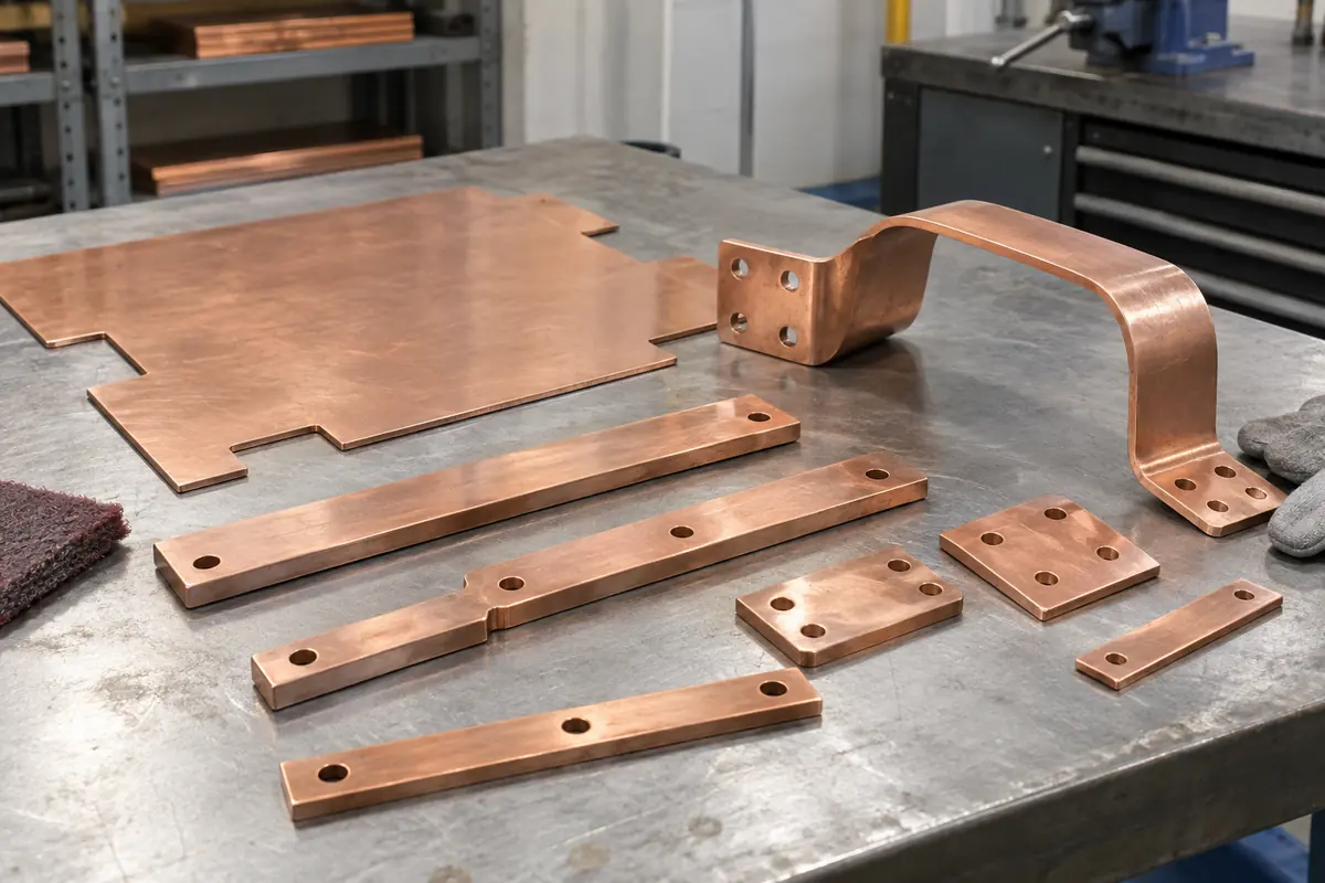
Control holes, bends, and contact regions
Formed copper parts need finished-state dimensions and a clear datum strategy.
Dimension hole patterns, slot geometry, bend angles, inside radii, formed offsets, stack interfaces, and clearance to neighboring parts. Identify finished dimensions after forming and plating.
Mark contact regions, masked areas, coating boundaries, and surfaces with functional finish requirements. Keep cosmetic notes separate from electrical-interface requirements.
- Finished hole and slot locations
- Bend radii, angles, and offsets
- Contact and masked regions
- Datums tied to assembly interfaces
| Feature | Drawing control |
|---|---|
| Contact pad | Location, size, finish, and protected area |
| Formed offset | Finished datum-to-datum geometry |
| Hole pattern | Fastener interface and positional requirement |
Define fabrication and finish scope
Cutting, holemaking, forming, deburring, plating, insulation, and assembly are distinct operations.
State which operations are included and name the approved finish or plating specification. Identify masking, rack marks, edge condition, burr direction, and any flatness requirement that supports assembly.
If insulation, lamination, welding, brazing, or dissimilar-metal joining is required, provide the approved design and process specification and confirm that the supplier scope supports it.
- Cutting and holemaking method constraints
- Forming and edge-condition requirements
- Finish or plating specification and masking
- Separately defined insulation or joining scope

Inspect geometry without implying electrical validation
Dimensional inspection confirms manufactured features; electrical and thermal performance require customer-defined validation.
Identify critical mounting, connection, and clearance features. Request inspection reports or CMM reports when the geometry and record are appropriate.
Material test reports can be requested for material traceability. Conductivity, temperature rise, dielectric, short-circuit, system safety, and certification testing are not implied.
- Critical connection and mounting geometry
- Finished-state dimensional inspection
- Material test report on request
- Customer-defined electrical and system validation
Busbar manufacturing follows the customer-approved electrical design
- Fabrication of customer-designed copper geometry within verified processes
- Approved finishes when specified and quoted
- Inspection and material records on request
- No implied ampacity, thermal, dielectric, fault, safety, or certification validation
Technical references
These primary references provide system context. Project requirements still belong in the customer-controlled drawing and specification.
Frequently Asked Questions
Can MakerStage determine a busbar current rating?
What should be called out for a contact area?
Which quality records are available?
Bring a controlled component package
Upload the model, drawing, quantity, revision, and requested records. MakerStage will review manufacturability against the supplied scope.
Start an RFQ